- Lyle Mays Remembering Lyle Mays - New YouTube Playlist with Unreleased Tracks from live Radio Broadcast
- Boss SY-1000 Interior Photos and Unboxing Photos
- Parker NiteFly SA with Factory Internal GK-2A Just Added! A profile of a Parker NiteFly SA with factory Roland GK-2A. Demos with Roland GR-100, GR-300 and GR-700. Behringer Deep Mind 12 The New Roland GR-700? Vintage Sounds in a Modern Analog Synth
- GR-300 Case Rare spotting of the Original Roland GR-300 Case!
- Roland Ready Les Paul Photos of Bob Welch's Custom Shop Les Paul Paul with Roland electronics.
- Peter Frampton With Roland G-303 Thank you Eric Fisher for finding this rare live video!
- Picture This 30th Anniversary Release - Wayne Scott Jones Album from November 1989.
- Converting the M-16C into an M-64C - Detailed tips on converting the M-16C into a M-64C with four times the memory capacity!
- Roland G-33 Major Update! 18 new photos, PLUS 4 YouTube videos!
- Switch Roland-Ready MIDI Guitar Complete details on the Switch Wild-IV, PLUS all the Switch Guitars!
- Boss GP-10 and Hex Fuzz Details on great hex fuzz sounds from the Boss GP-10
- Steve Hackett - Roland GR-500/GS-500 Performance - Please Don't Touch From the 'Please Don't Touch' tour, November 8, 1978. Great GR-500 showcase!
- Vintage Roland GR-300 Review from Electronics & Music Maker - Nov 1981
- Roland GR-77B for Reaktor - Download a modeled Roland GR-77B for Native Instruments Reaktor 5!
- Roland GR-700 Blue - Remake with 'GR-300' blue finish, new handles, and handsome natural wood end blocks! Thank you Chuck Nin!
- PG-200 - Updated NOS New-Old-Stock photos of the Roland PG-700, programmer for the Roland GR-700. Thank you Eric Rusack!
- G-707 White Ever wonder what a G-707 would look like redone in a brilliant white finish? With Steinberger folding leg rest!
- 3D Printing Vintage Roland Guitar Parts - 24-to-25 pin Plate - Courtesy of Jusin Casey
- David Gilmour - Solo with Roland STK-1 and GR-700!
- Moog Voyager XL (with Casio MG-510 Cameo) Space Music - Melodic Downtempo, Ambient, Ambient& PsyChill Mix.
- Roland GM-70 Guitar-to-MIDI Converter - Review by Paul White, Music Technology Magazine, April 1987
- Theme from M*A*S*H. Arranged using only the ARP Odyssey for all sounds, synths, drums, efx, etc.
- Ibanez IMG2010 - Owned by George Benson. Rare 'Endorsee' finish with Silver hardware.
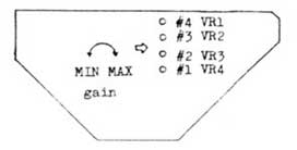
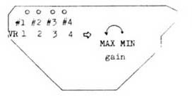
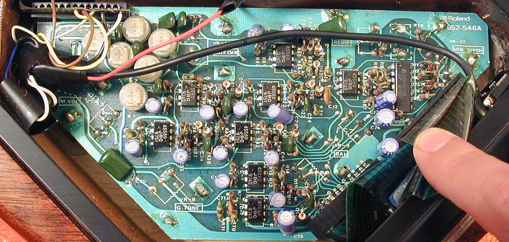
G-202/G-303/G-505 and G-808 Electronics Compared:
 and the G-303/G-808 (below). The layout is basically the same.") |
| The above photo shows the G-505 electronics card (top) and the G-303/G-808 (below). The layout is basically the same. |
 controls with the G-505 (top). The G-303/G-808 controls are slightly raised and not fixed to the board") |
| Compare the G-303/G-808 (lower photo) controls with the G-505 (top). The G-303/G-808 controls are slightly raised and not fixed to the board |
The basic layout is the same for both the G-303/G-808 and the G-505. The main difference is the kind of trimmers used for the cards. The G-303/G-808 has slightly larger trim pots than the G-505. However, the trimmers for the G-505 are arranged in a row. The G-303/G-808 has staggered and slightly offset trimmers.
The G-505 has holes in the access plate allowing the player to adjust the trimmers without removing the back plate. For G-303/G-808 users, the rear electronics cover must be removed to adjust the trimmers.
The only other difference between the two cards is the method used for mounting the controls. On the G-303/G-808, most of the controls "float" on stiff wire, supported by brackets, rather than being attached to the board. This is to accommodate the carved top of the G-303/G-808 . The G-505 controls are mounted directly to the electronics card.
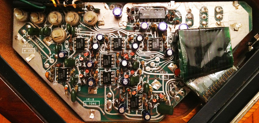
The G-202 board is in many ways a simplified version of the G-303/505/808 board. The hex fuzz uses a single gain stage, and the circuit board itself uses a crude dual-layer design.
 and the G-505 (below).")
The above photo shows the G-202 electronics card (top) and the G-505 (below).

The G-202 board is a simplified version of the G-303/505/808/LPK-1 board.

The smaller G-707/STK-1 card, designed without the hex fuzz circuit.
Ibanes IMG-2010 Electronics


The IMG-2010 improves on the standard Roland package in three ways: first, only the IMG-2010 has control voltage buffering circuits for control voltage stability.
Secondly, the trimmers in the IMG-2010 adjust the output string level from 60% to 100%, rather than the 0% to 100% on the Roland guitars. By limiting the control range, there is more precise control over the string output level.
And finally, the IMG-2010 does not use the fragile ribbon connector found in every Roland guitar. Instead, individually insulated solid core wires connect the electronics board with the 24-pin connector. The Roland ribbon connectors become brittle and easily crack with age. The IMG-2010 does use a ribbon connector to connect the hex pickup, but only the IMG-2010 cable has reinforcing backing.
Individually insulated solid core wires connect the electronics board with the 24-pin connector. In addition, the IMG2010 has control voltage buffering circuits for control voltage stability.
Versions - Electronics:
 |
| Early Card Serial Number 030499 and lower |
 |
| Later Card Serial Number 040500 and higher |
 |
| Early Card Serial Number 030499 and lower |
 |
| Later Card Serial Number 040500 and higher |
There are two versions of electronics cards for the Roland G-33 and G-88 basses. The most distinctive difference in the two cards is the placement of the string level trim controls. On the early basses, the trimmers are placed in a verticle alignment.
On the later cards, the string trimmers are placed in a horizontal alignment. Otherwise, the actual circuit designs appear to be the same. The Roland service manual notes that basses with serials numbers 040500 and later have the horizontal trimmers, and serial numbers 030499 and lower have the verticle. Basses in the range from 030400 - 040599 could possibly have either electronics card.
Version History PC Boards A - B - C:
|
|
|
Version A - Click on image to enlarge
|
|
|
|
|
Version B - Click on image to enlarge
|
|
|
|
|
Version C - Click on image to enlarge
|
|
Like the GR-300, there are three versions of the G-303 and G-808 guitars, distinguished by changes to the PC board.
I was contacted by a G-303 player in the States and a G-808 player in Norway both using the first run, early "prerelease" version of the guitar electronics. The cards are labeled as version "A." The published Roland documentation supports version "B: and "C."
These rare "A" cards are unusual in several ways: the component layout is very different and the outputs trimmers seem to be arbitrarily placed on the board. You can also see jumper wires soldered across the board. In addition, the standard 1/4” output jack solders directly to the PCB, rather than the ribbon connector.
The first time I tried to repair a failed op-amp in a G-303, I realized that the pin-out documentation was wrong on the schematic. The pin out information was correct on the G-505 Service Manual Schematics schematic, which uses almost the same circuits.
All the G-303s and G-808s that I have checked have op-amp pin outs consistent with the G-505. Which made me wonder if the op-amp information in the original G-303/G-808 Service Manual Schematics refers to the very rare "version A" board.
It is difficult to see in the photos, but on the standard cards, version "B" and "C", three op-amps, IC1, IC2 and IC3 are used to amplify the signals to line-level for the GR-300. These op-amps are the top three 4558 op-amps in line with the 24-pin ribbon connector. IC4, IC5 and IC6 op-amps are used to create the hex fuzz sound. This is consistent with the G-505 schematic. The line-level amplifiers are surrounded by resistors for a simple gain circuit, and the hex fuzz amplifiers have the network of diodes used to create the fuzz sound.
From looking at the version "A" photo, it appears the one op-amp is used per string to both amplify the signal and create the hex fuzz sound. If you look at IC6, at the top of the version "B" and "C" card, you can see resistors just to the left of the chip creating gain in the negative feedback loop, and additional diodes just to the right side of the chip for generating fuzz. This is consistent with the G-303/G-808 schematic.
Version History "Wide" (12 mm) and "Narrow" (10 mm) Pickups
 |
|
|
10 mm "narrow" 80 ohm pickup on the left next to 12 mm "wide" 900 ohm pickup installed in a late model G-808.
|
|
 |
|
|
"Narrow" pickup installed in a G-303. This is one of the earlier models, and has the high-gain circuit.
|
|
 |
|
|
"Wide" pickup installed in a G-303. This is one of the later models, and has the low-gain circuit.
|
|
After years of working with Roland vintage electronics, I finally noticed that there were two variations on the familiar hex pickup. One pickup is small, with an impedance of 80 ohms, and the other pickup is slightly larger, with an impedance of around 900 ohms. For my purposes, I labeled these pickups as "wide" or "narrow." One pickup is around 10 mm wide, and the other is about 12 mm wide. Generally, the narrow pickup seems more common in earlier guitars, and the wider pickup is common with the later models.
I had been exchanging emails with GR-user Jonathan Prince, who had, once upon a time, ordered a replacement hex pickup from Roland. He mentioned he had misplaced the paper they sent with the pickup explaining what parts to replace when he installed the new pickup. I emailed back that his memory was probably fooling him, as there was no official Roland documentation on the pickup change. And then...low and behold...Jonathan sent me this memo from Roland! Dated July 6, 1995, from a Mr. Mark Wire, it lays out all the technical information on the pickups that I had only surmised! View the original note from Roland sent to Jonathan Prince.
"We don’t have any humbucking pickups for your G-808 (I physically went out to parts dept. to check.)" begins the note! Well, that is some bad news! But Mark Wire was able to find a replacement hex divided pickup! And Mark notes the serial numbers of the new and old pickups: Old type: #601 Pick-Up 22380601 New type: #610 Pick-Up 22380610.
Mark lists the serial numbers of guitars that use the older style, #601 (or part number 22380601) divided pickups:
G-202 before serial no. 411600
G-303 before serial no. 413100
G-505 before serial no. 412600
G-808 before serial no. 413100
Mark goes on to outline the resistors that need to be changed for the new #610 pickup. As it turns out, these are exactly the modifications that I outline in the notes below. For the G-303, G-505 and G-808, each string needs two resistors changed, one effecting the synthesizer signal, and the other effecting the hex fuzz signal. The G-202 has a different hex fuzz circuit, so only six resistors need to be changed.
I also have to add this: I picked up some G-707 electronics pulled from a guitar some years ago, and I did find a G-707 circuit board wired to support the older, narrow pickup. In the case of the G-707 guitar, you need to check to following resistors: R23, R26, R29, R35 and R38. According to the schematic, these resistors should be 10K, but in this rare G-707 circuit board, the resistors were only 1K. This 10:1 ratio difference is in keeping with all the other changes.
When switching from the 80 ohm (narrow) to 900 ohm (wide) pickup, there is a 10:1 increase in impedance, likewise, it is necessary to change the negative feedback loop resistor by a similar 1:10 ratio, from 330K to 33K, and from 1 M to 100K.
Mark also mentions that the pick guard must be slightly enlarged to accommodate the wider pickup, but only on the G-202 and G-505, the only guitars with pickguards. Also, while I measured these pickups as 10 mm and 11 mm respectively, Roland has them listed as 10 mm and 12 mm in size.
One more thing that I must mention: apparently Mark Wire did not have any official Roland stationary when he penned this missive to Jonathan. So, and I think this is the coolest part of this whole note, he apparently decided to trace out the official Roland Company logo at the top of the note. I mean, nothing says official Roland service notice like a hand drawn Roland logo! I have never met Mr. Mark Wire, but I sure like his dedication to customer satisfaction! Not only did he personally check the parts department to see if he could find a G-808 pickup, but he took the time to add the Roland logo to this note! Excellent!
 |
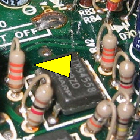 |
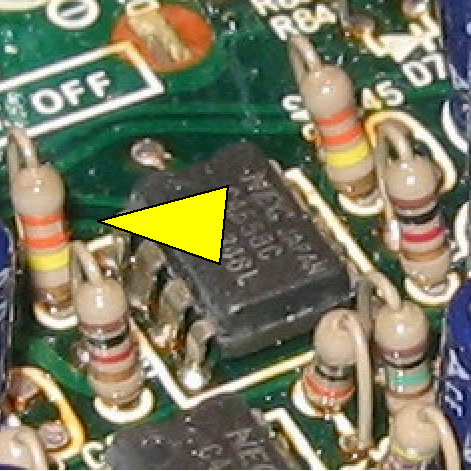
| High Gain Circuit: the yellow arrow points to a 330K resistor in the negative feedback loop of the G-303/808/LPK-1 board. | Low Gain Circuit: the yellow arrow points to a 33K resistor in the negative feedback loop of a different G-303/808/LPK-1 board. |
"Narrow" (10 mm) Pickup - Uses High Gain Circuit
"Wide" (12 mm) Pickup - Uses Low Gain Circuit
You need to actually check your own card with a multi-meter, or read the resistor values to see what you have. I worked on a LPK-1 card which had the 330:1 gain structure for the "narrow" pickup, rather than the 33:1 design shown in the LPK-1 schematic.
When I installed the correct "wide" pickup for the 33:1 circuit, the LPK-1 would work with the GR-300, but the internal trimmers were very sensitive. After a quarter-turn, the gain would be too high for any kind of dynamic control. The solution was to replace the 330K resistors with 33K resistors. After this change, everything worked perfectly. I also checked the gain settings with the more sensitive GM-70, because the ladder LED display gives a much more accurate reading than one red LED on a GR-300.

|

|
|
Primary Resistors: Click image to enlarge
|
Hex Fuzz Resistors: Click image to enlarge
|
The yellow arrows in the first picture on the left point to replacement resistors R12, R22, R32, R42, R52 and R62 in a LPK-1 board. The original brown 330K (5% tolerance) resistors were replaced with blue 33K (1% tolerance) resistors. These resistors set the gain for the synth signals.
The yellow arrows in the second picture point to replacement resistors R14, R24, R34, R44, R54 and R64 in a LPK-1 board. The original brown 1M (5% tolerance) resistors were replaced with blue 100K (1% tolerance) resistors. These resistors set the gain for the hexaphonic fuzz circuit.
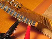
Checking the Impedance of the Divided Vintage GR Synth Pickup
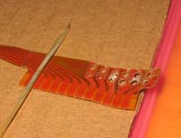
A vintage Roland GR pickup consists of the divided pickup plus an attached ribbon cable. Be careful when working with these pickups, as the ribbon cable will become brittle with age and is easily damaged. There are 12 contact points on the ribbon cable. The first seven are for the hex pickup, and they include a common or ground point, plus the six string outputs. Reading from the long edge of the ribbon to the solder points, the outputs are strings #4, #3, #1, #2, ground (common), #5 and #6.
The next five contact points are actually for attaching wires to the top panel guitar electronics. Reading in the same direction, they are the p-touch, p-touch lock, the guitar pickup output, ground, and the normal guitar out. Refer to the diagram below from the Service Manual Schematics.
 |
 |
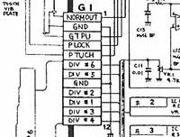 |
| L-R, strings 4, 3, 1, 2, ground, 5, 6, p-touch, p-lock, guitar pickup, ground and normal output. | Using a multimeter to test string #3 for resistance. A working element should read 78 to 80 ohms. | Diagram from the Roland Service Manual Schematics showing the wiring of the ribbon connector. |
To test each element in your pickup, attach the ground lead from a multimeter to the ground (common) contact point for the hex pickup, then move the positive test lead to the various pickup outputs. Depending on whether you have a wide or narrow pickup (see above), a working pickup element should read 80 to 90 ohms for the narrow version, or 800 to 900 ohms for the wide version. If you read between two pickup output points, you should see 160 ohms or 1.6K (depending on the version of pickup). This is double the reading of an individual pickup. If you get a reading of 0 ohms, or an open circuit reading (infinite resistance), then you likely have a damaged pickup.
Version History - The LEDs that never happened:
Unlike the previous Roland guitars, there is not much archaeological drama to the Roland G-707 guitar. The only differences I have detected are very minor changes to the guitar electronics package. The G-707 Service Manual Schematics makes note of LEDs, but provides no details. A closer look at the G-707 electronics card shows that there were provisions to include two power LEDS on the G-707 guitar, one for the positive 15 volt supply, and one for the negative 15 volt supply.
I have seen some cards with current-limiting resistors for the diodes in place, and some with them left off, while the silk-screening still shows the LED options. Consider this, if the G-707 was not striking enough, apparently Roland seriously thought about including glow-in-the-dark diodes on the guitar!
|
|
|
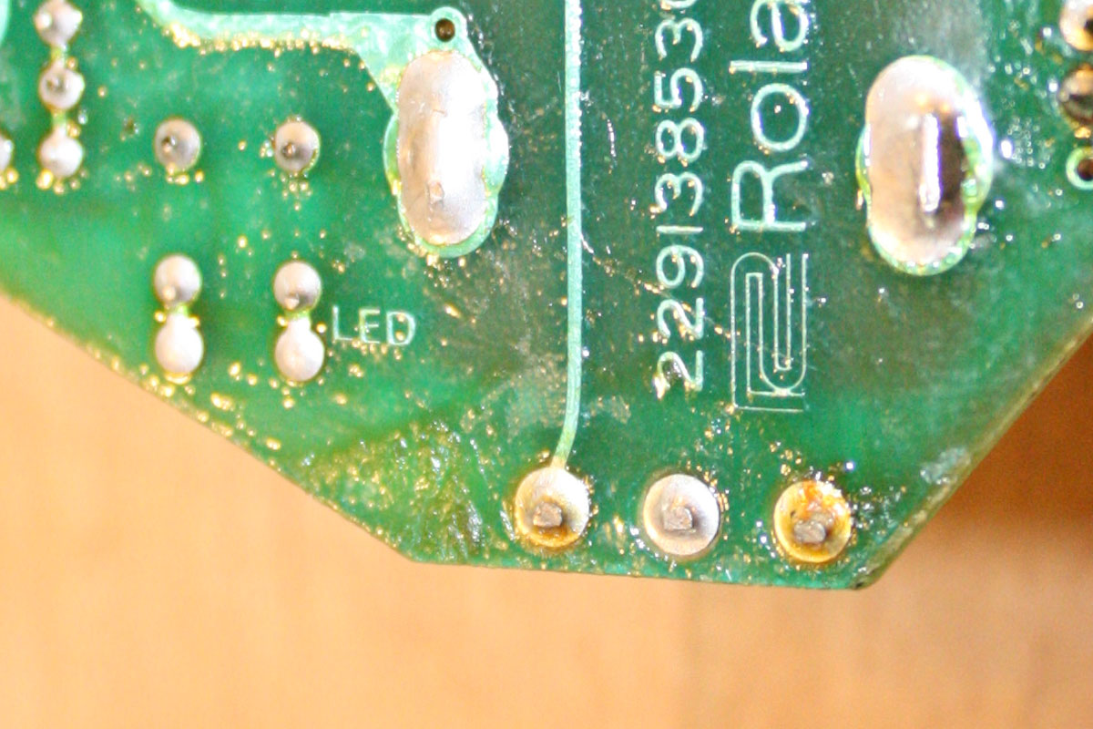
| Resistors R16 and R17 for LEDs on the Roland G-707. | A different G-707 PC board without resistors R16 or R17 installed. | Screened on the back of R16 and R17 is the legend for "LED" |
| Click on any image for larger view. | ||
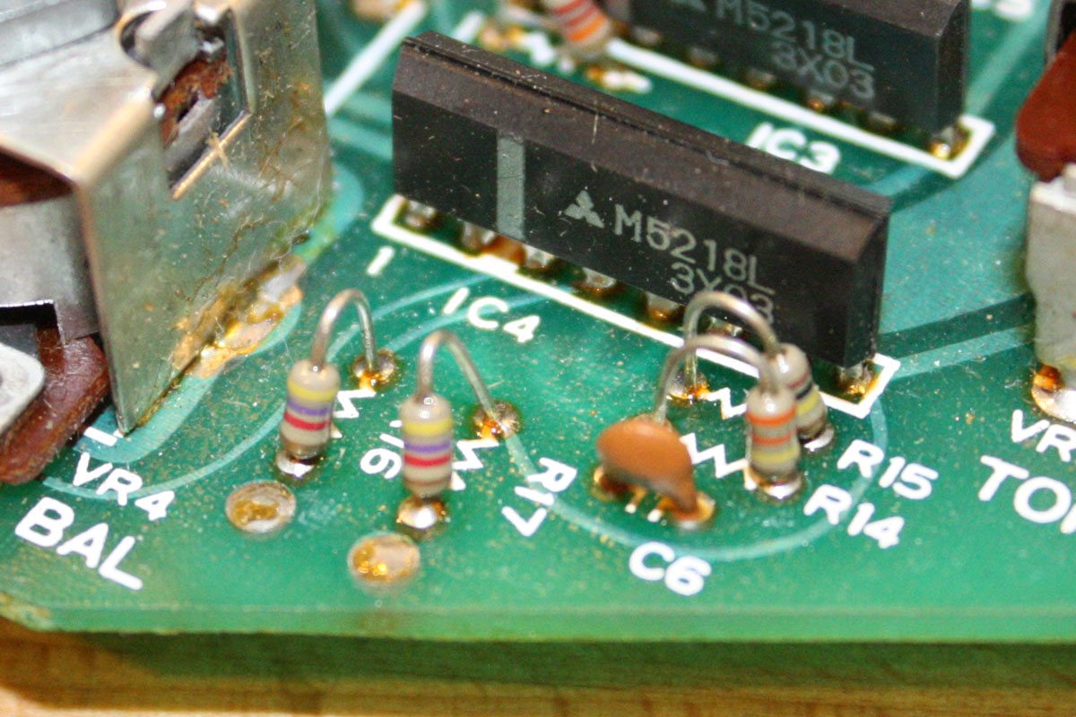
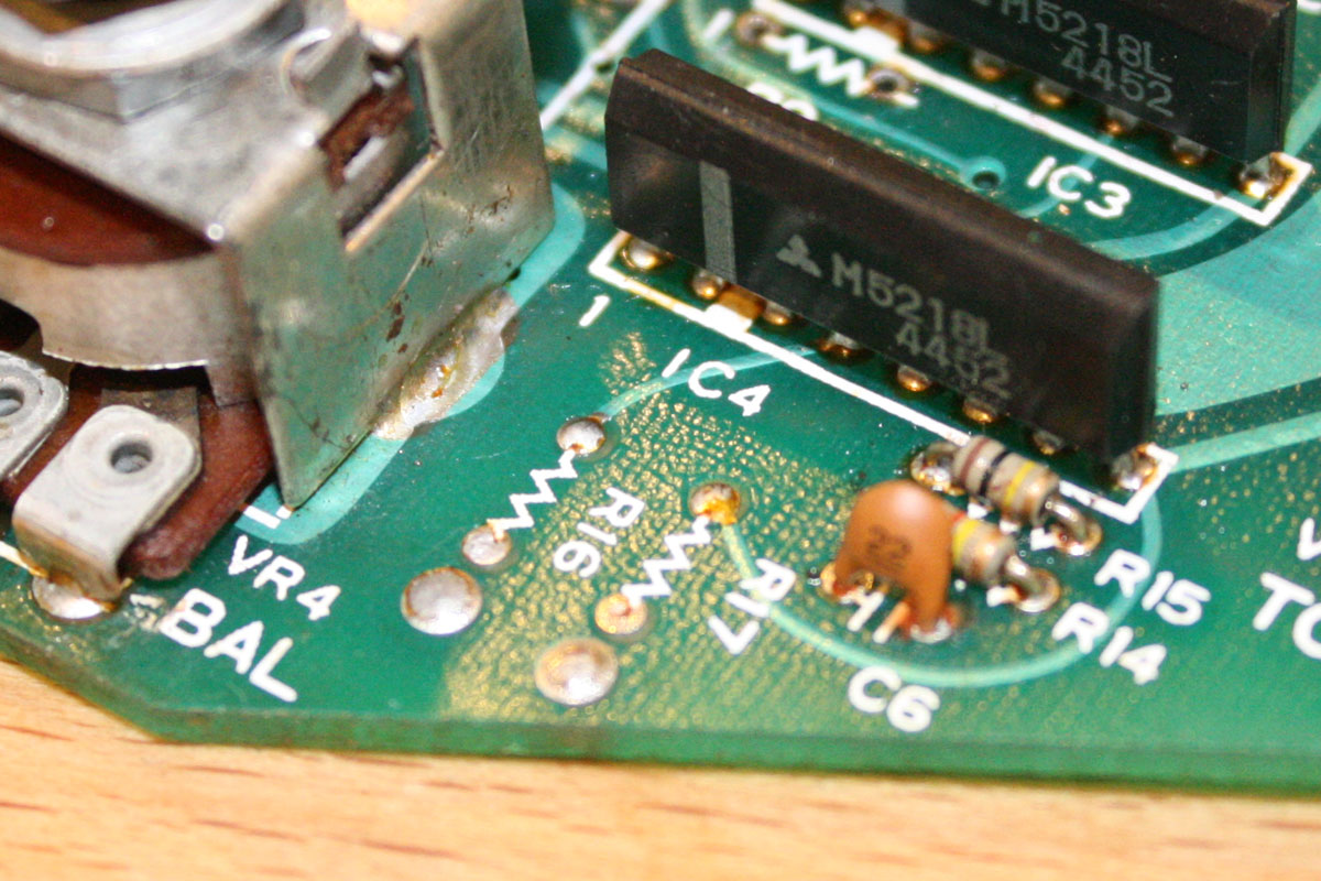
Version History - Buffering the Volume Control Voltages:
The G-707 Service Manual Schematics also shows a buffering option the guitar and synth volume control voltages, but the buffering section, utilizing IC#5, is crossed out on the diagram. Like the diode variation, some cards do an operational amplifier in place, and some leave it off. IC#5 is a M5218, a popular inline dual operational amplifier. The M5218 is also used in the G-77, Ibanez IMG2010 and the Steinberger Roland-Ready guitars.
A little explanation: if the connected synthesizer "loads" the volume control voltage, the guitar synthesizer may have its volume reduced. So rather than reading a full 11 volts, the voltage may be reduced to 10 volts. Maximum volume on a vintage Roland synth is a control voltage of around 11 volts, expressed on pin 9, as synth volume, and on pin 10, as guitar volume. Pin 8 supports master volume, though this is mostly ignored by the vintage Roland synthesizers. The design of the Roland US-2 reduces the synth voltage slightly, meaning that synths played though a Roland US-2 are not as loud as they would be without the US-2.
By providing a buffer, it is less likely that the attached guitar synthesizer will reduce the synth volume output voltage. The G-707 was the first Roland guitar synth to incorporate a buffer circuit. The G-202/303/505/808 did not have a buffer circuit. Apparently Roland engineers had mixed feelings about the need to buffer the volume voltages, since as noted this feature is crossed off on the Service Manual Schematics schematic, though I have seen some G-707 cards with this feature in place.
G-707 Electronics Card with IC#5 Buffer Chip: S/N 2291385302.
G-707 Electronics Card without IC#5 Buffer Chip: S/N 2291385303.
A check of the Roland G-707 Service Manual Schematics shows that it only lists part number 2291385303. There is no mention of the earlier 2291385202 card which includes IC#5. Check out the photos of the STK-1 kit, based on the G-707 card. The STK-1 electronics card in the photos is the earlier version with both IC#5 buffer and the LED resistors.
 installed with associated resistors.")
|

|

|
| G-707 electronics card with IC#5 (on left) installed with associated resistors. | A different G-707 PC board without IC#5 and associated resistors. | Roland G-707 Service Manual Schematics with IC5 shown as a buffer amplifier, but crossed out. |
| Click on any image for larger view. |
||
EMI Filter on the GM-70 and GR-77B:
For a brief period Roland installed EMI filters on some of the guitar synth products. Some GR-77Bs and BAK-1 kits have a modified 24-pin ribbon with 16 1K ohm resistors installed to control EMI signals. And a few GM-70s, early models, had a more elaborate system with similar resistors, and some additional filters, to control EMI signals.
Only the power supply lines and ground connections are unaffected.


