- SY-100 Expression Pedal Shoot Out! Comparing the Roland EV-5, Boss EV-30, Moog EP-3 and Mission Engineering SP-1
- SBC-1324 New Videos Posted!
- BX-13 Do-It-Yourself Cooper tracing and silk screen available for download.
- Roland Centerstage - Roland Makes !t Happen! 1984 Winter Namm - First time ever!
- Boss SY-1000 All About Program and Bank Change Commands - Boss SY-1000 Webpage
- Boss SY-1000 All About Program and Bank Change Commands YouTube Video
- Email Blast Archive! 4 Years Plus of Email Blasts Archived.
- Roland BC-13 Full review on YouTube
- NEW Interior Photos - First time ever!
- The Most Requested GR-700 Patch A breakdown of how to recreate the classic Roland GR-700 Factory Patch 3-5, "Lead II" as used by Glen Tipton of Judas Priest, adding a signature sound to the excellent track 'Turbo Lover'.
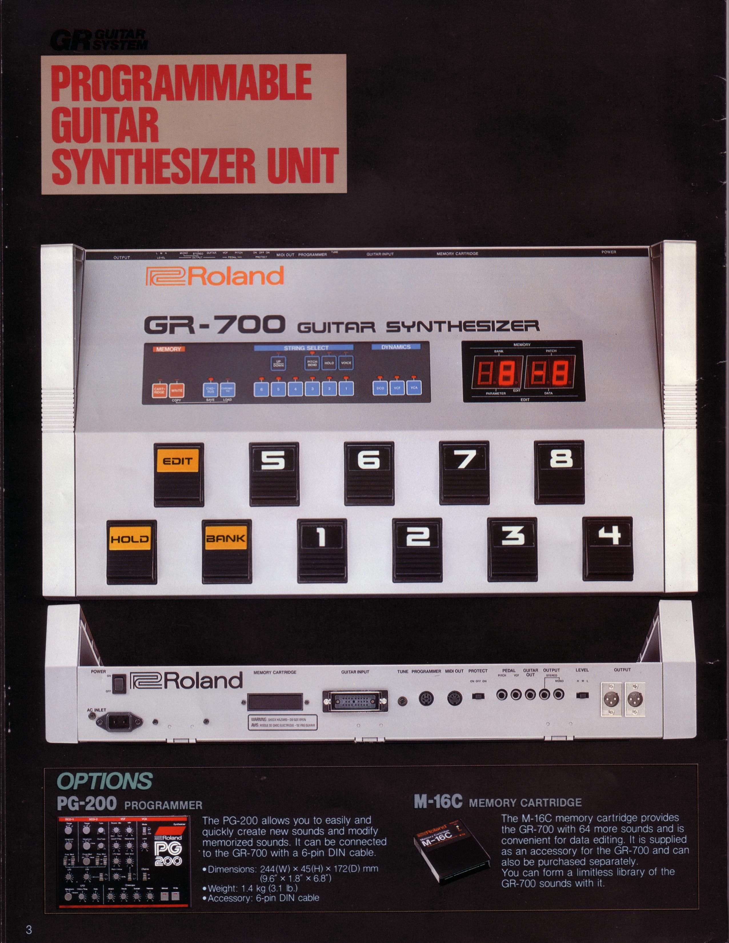
- High Res PG-200 Manual (NEW) NEW! I tracked down a mint PG-200 Owner's Manual, newly posted.
- Roland GR-500 MINT Stunning Photos As seen on Reverb! A really stunning example of a Mint Roland GR-500/GS-500 combination. Includes the very, very rare GR-500 case, never seen before!
- The Swallow's Dream is a performance piece made only using sounds from the Boss SY-1000 with an Epiphone Dove Pro equipped with the Graphtech GHOST Acoustic Steel String Midi Kit.
- Mastering Resynthesis with the SY-1000 This video shows how to record the master stereo output of the SY-1000 in the USB audio to a stereo track. In this way many tracks of guitar synthesizer can be recorded and layered to create a final composition.
- Epiphone Dove Pro with Graphtech GHOST Midi Kit In this video I share a few insights about a Epiphone Dove Studio Acoustic-Electric Guitar Vintage Burst I purchased with the Fishman Sonitone and Sonicore System and the Graphtech GHOST Acoustic Steel String Midi Kit installed.
- Roland GM-70 MIDI Polyphonic Expressions: Using the vintage Roland GM-70 with the Arturia Pigments Soft Synth with MPE MIDI Polyphonic Expressions
- Roland GM-70 Alternate Tunings and MIDI Continuous Controllers: Using the vintage Roland GM-70 alternative tunings, and assigning MIDI continuous controllers
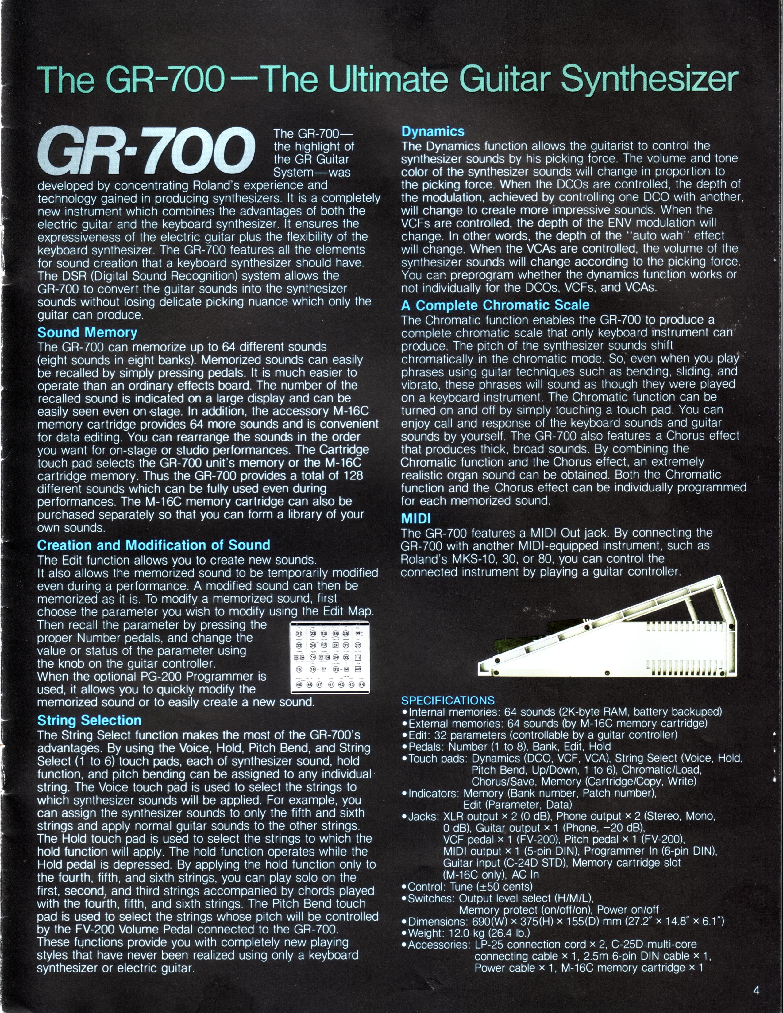
- Roland Hardware GR-700: Vanguard to Synth Frontiers: Announcing the Roland GR-700! From the Roland Users Group, Volume 2, Number 4
- Boss SY-1000 On The Run Sequence - Step By Step Tutorial - EMS Synthi AKS - Analog Recreation: This is a step-by-step tutorial showing how to recreate the famous 'On The Run' sequence from Pink Floyd's album The Dark Side of the Moon.
- Boss SY-1000 Guitar Synthesizer Sequence Step By Step Dynamic Synth Tutorial: Tutorial on using the Sequencer in the Boss SY-1000.
- Jeff Baxter - How I Became An Electronic Musician: Read this interview with guitarist Jeff Baxter from the first issue of the Roland User's Group Magazine.
- Boss SY-1000: Resynthesis - YouTube Video: Multitrack Guitar Synthesis Recording
- Boss SY-1000 Reaktor 6 - DIY Build Your Own Guitar Synth YouTube Video: Use Reaktor with the Boss SY-1000 to build your own software guitar synthesizer.
- Korg MS-03 Forget MIDI! Forget the Hex Pickup! Direct Guitar to Analog Synthesizer with the mighty Korg MS-03 and the Arp Odyssey and Behringer K-2 (Korg MS-20)
- Korg MS-03 Video - Demo of the RareKorg MS-03 with the (Korg) Arp Odyssey and the Behringer K-2 (MS-20 Clone)
- Roland SPV-355 Guitar to Synthesizer Video - Roland G-303 Direct to the Roland SPV-355
- Behringer K-2 Guitar to Synthesizer Video - The hidden Guitar Synthesizer in the Behinger K2!
- GR-700 Tech Tips from Roland! Originally published in the Roland User Group magazine, Volume 2, Number 4.
- GR-700 Performance Tips! Originally published in the Roland User Group magazine, Volume 3, Number 3.
- Guitar Greats and the GR-700 Originally published in the Roland User Group magazine, Volume 2, Number 3.
- Roland Hardware - GR-700 G-707 Originally published in the Roland User Group magazine, Volume 2, Number 3.
- Synth Ethics Featuring the Roland GR-700 Tips on using the GR-700 from Mark Wood, Guitarist Magazine May 1985
- Three Favorite GR-700 Patches By Steve Carnelli, Guitar PLayer June 1986.
- Roland GR-700 Guitar Synthesizer Product Review By John Themis Guitarist May 1985
- Pat Metheny and Lyle Mays Interview - 1989 Pat and Lyle interviewed during the height of the popularity of the Pat Metheny Group in Music Technology Magazine.
- Pat Metheny Interview - 1985 Vintage interview from the era of 'First Circle', and 'The Falcon And The Snowman' - Guitarist Magazine
- Pat Metheny Interview - 1984 Vintage interview from the Roland Users Group covering Pat's early career as musician and highlighting the Roland GR-300.
- Boss SY-1000 Recreating the Pat Metheny GR-300 Solo Sound YouTube Video detailing tweaks to recreate the dramatic Pat Metheny GR-300 solo sound with the Boss SY-1000.
- Pat Metheny - New England Digital Synclavier Demonstration YouTube Video Old Grey Whistle Test - Roland G-303
- Pat Metheny with NED Synclavier Prototype YouTube Video Early Guitar Synthesizer Controller
- Pat Metheny and the NED Synclavier Read Pat's notes on using guitar synthesizers and the New England Digital Synclavier.
- Van Halen Michael Anthony Roland GR-33B G-33 Bass Guitar Synthesizer Solo YouTube Video From 1982 Largo and 1983 Devore In Concert Live Performance! FILTER SWEEPS!!! DELAYS!!!
- Spicetone 6Appeal Guitar Processor Analog Hexaphonic Distortion Pedal The Spicetone 6Appeal is a modern take on the poly distortion, hexaphonic (hex) fuzz pedal.
- GR-100 GR-300 Power Supply Repair New video on the one GR-100 or GR-300 or GR-33B power supply mod you MUST do!
- Roland GR-D Interior Photos: First time on the web! Interior photos of the Roland GR-D!
- Gibson Les Paul Custom LPK-1 Repair In depth step-by-step repair of the Gibson Les Paul with LPK-1 kit.
- Roland G-303 A Fresh Look! Trevor Harley sent me these photos of his Roland G-303. The guitar was refinished with a flame maple top and back by the Canadian Luthier George Furlanetto. Note that the touch pads have been relocated below the bridge pickup.
- Steinberger Time! Newly posted photos of a White Steinberger GL-4T-GR
- Ultimate 24-Pin Custom Guitar Stunning photos of the most amazing custom built 24-pin guitar ever made! The solar system on the fret board and more!
- More PINK Please! Hamer Phantom A7 Nothing says vintage 80s guitar styles link a solid pin finish! Samuel Cuevas sent me a few photos of this very, very rare pink Hamer Phantom A7 Roland-Ready guitar.
- Boss SY-1000 with Roland G-33 YouTube video with a demonstration of all 200 Bass patches for the SY-1000
- BAK-1 Videos A new video on the BAK-1 Electronics card, plus comparison of the G-88 and G-77 electronics
- BAK-1 Photos Newly posted photos of the BAK-1 Bass Guitar Synthesizer Installation Kit
- Roland G-33 G-88 G-77 BAK-1 Vintage Analog Bass Guitar Controller Assembly - Comparison
- G-77 Fretless First time on the web! New photos from Skylark of his pristine G-77 Fretless bass.
- Clone 24-Pin Cable At long last there is a quality clone of the impossible to find Roland 24-pin cable. This is a quality, made in the U.S.A. cable produced by 'MagicTrashMan' in North Carolina. Check out the description and video on the cables page.
- Roland GR-500 Mods - Part 1 Thanks to the Phantastic Jimi Photon who pointed me to the March April 1981 Polyphony magazine with the first list of Roland GR-500 modifications.
- Boss SY-1000 All Bass Patches! Complete on YouTube (no talking)!
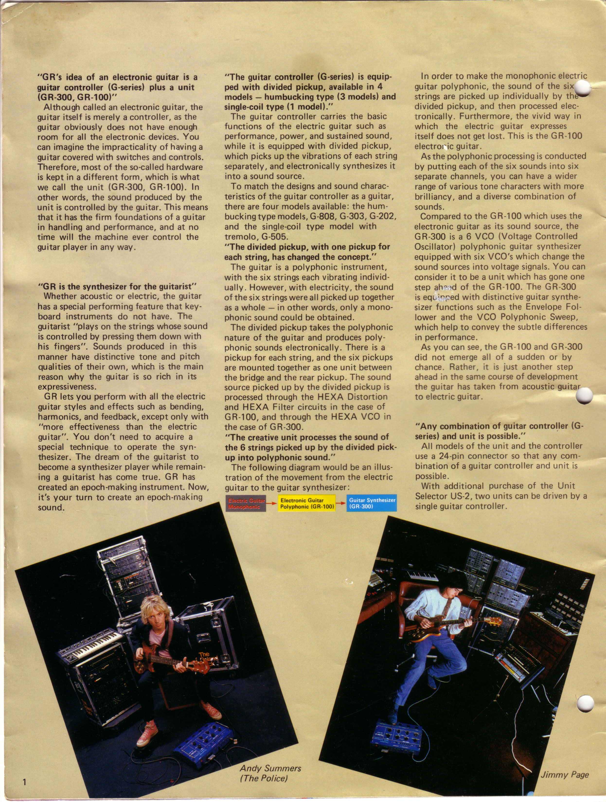
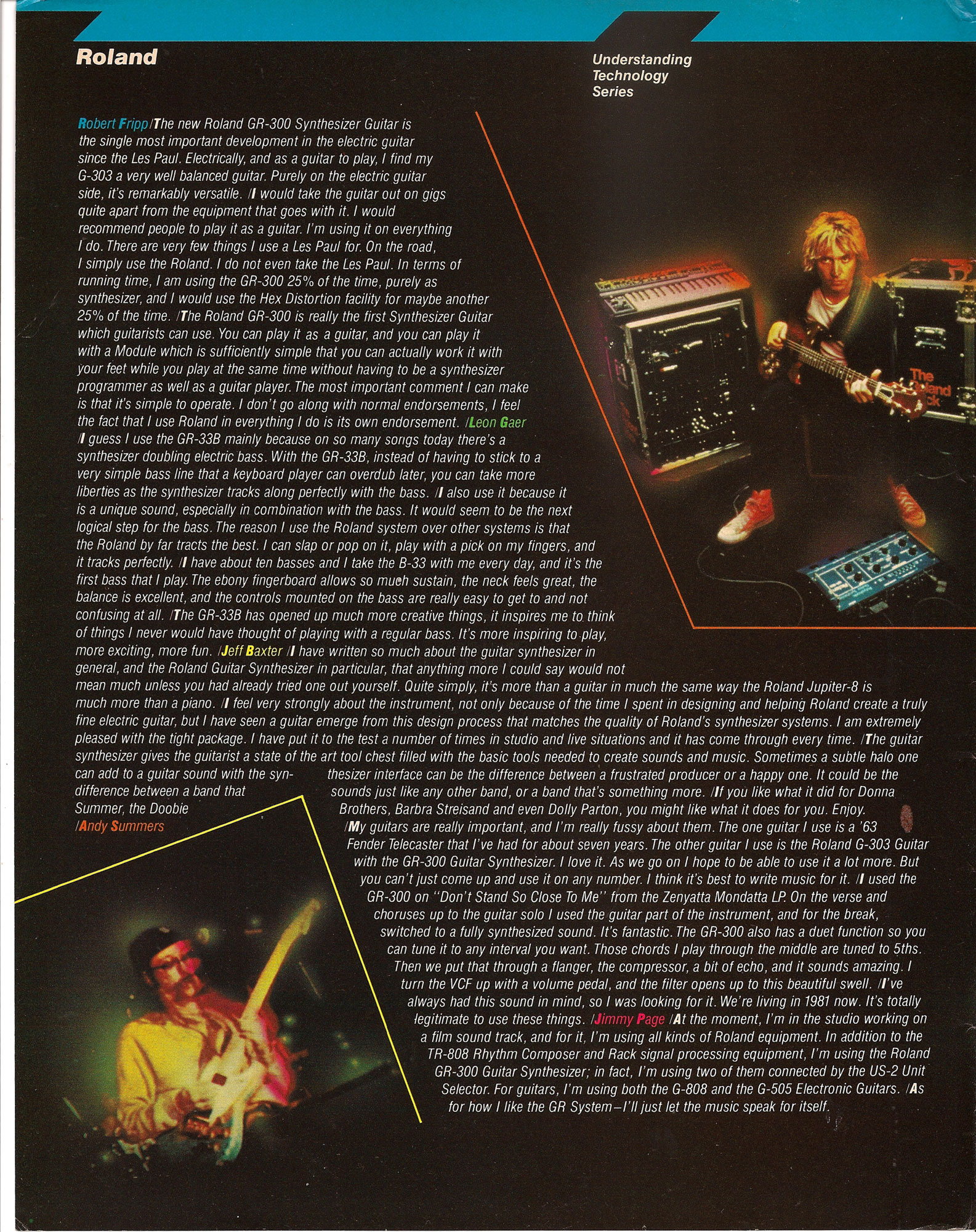
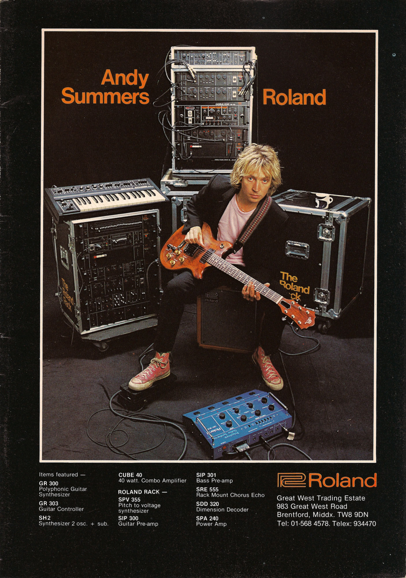
- Read The Full Interview The year was 1983, and the Police were exploding on the charts. The inventive and adventurous Andy Summers was busy rewriting what a rock guitar player could be. The smash hit "Don't Stand So Close To Me" prominently featured the Roland GR-300, played by Andy with the Roland G-808. Volume 2, number 2, of the Roland Users Group magazine featured a great interview with Andy, reproduced for the first time on the web!
- Read The Full Review Roland shifts direction in 1987, releasing the Roland GK-1 and GM-70. This combo said goodbye to Roland guitars and dedicated guitar synthesizers like the GR-300 and G-808 in favor of a system that could be mounted on any guitar, and used to control any MIDI synthesizer. Read Warren Sirota's review of the GK-1, GM-70, and the MKS-50 and MKS-70.
- Roland GR-500 Mods and Tips! Electronic Musician magazine started life as Polyphony magazine, edited by young writer named Craig Anderton. Seemingly produced by on a single typewriter in the early eighties, this Polyphony article features insights and modifications for the Roland GR-500!
- History of the Guitar Synthesizer Travel back in time, before MIDI, before the Roland GR-700, to the early 1980s, when the Roland GR-300 was the pinnacle of guitar synthesizer technology.
- Steve Howe and Steve Hackett Prog Rock Guitar Titans Teamed up for GTR, Chart-Topping Band Centered around the Roland GR-700!
- Steve Howe Roland Profile A detailed profile of Steve Howe, his Roland G-505 and GR-700 from the 1984 Roland Users Group Magazine
- Boss SY-1000 Tutorial Videos New vidoes on setting up Guitar-To-Midi and blending normal guitar sounds with modeled sounds.
- Washburn JB100 Profile A look at the Washburn Roland-Ready JB100. Detailed photos and videos!
- Lyle Mays Remembering Lyle Mays - New YouTube Playlist with Unreleased Tracks from live Radio Broadcast
- Boss SY-1000 Interior Photos and Unboxing Photos
- Parker NiteFly SA with Factory Internal GK-2A Just Added! A profile of a Parker NiteFly SA with factory Roland GK-2A. Demos with Roland GR-100, GR-300 and GR-700.
- Behringer Deep Mind 12 The New Roland GR-700? Vintage Sounds in a Modern Analog Synth
- GR-300 Case Rare spotting of the Original Roland GR-300 Case!
- Roland Ready Les Paul Photos of Bob Welch's Custom Shop Les Paul Paul with Roland electronics.
- Peter Frampton With Roland G-303 Thank you Eric Fisher for finding this rare live video!
- Picture This 30th Anniversary Release - Wayne Scott Jones Album from November 1989.
- Converting the M-16C into an M-64C - Detailed tips on converting the M-16C into a M-64C with four times the memory capacity!
- Roland G-33 Major Update! 18 new photos, PLUS 4 YouTube videos!
- Switch Roland-Ready MIDI Guitar Complete details on the Switch Wild-IV, PLUS all the Switch Guitars!
- Boss GP-10 and Hex Fuzz Details on great hex fuzz sounds from the Boss GP-10
- Steve Hackett - Roland GR-500/GS-500 Performance - Please Don't Touch From the 'Please Don't Touch' tour, November 8, 1978. Great GR-500 showcase!
- Vintage Roland GR-300 Review from Electronics & Music Maker - Nov 1981
- Roland GR-77B for Reaktor - Download a modeled Roland GR-77B for Native Instruments Reaktor 5!
- Roland GR-700 Blue - Remake with 'GR-300' blue finish, new handles, and handsome natural wood end blocks! Thank you Chuck Nin!
- PG-200 - Updated NOS New-Old-Stock photos of the Roland PG-700, programmer for the Roland GR-700. Thank you Eric Rusack!
- G-707 White Ever wonder what a G-707 would look like redone in a brilliant white finish? With Steinberger folding leg rest!
- 3D Printing Vintage Roland Guitar Parts - 24-to-25 pin Plate - Courtesy of Jusin Casey
- David Gilmour - Solo with Roland STK-1 and GR-700!
- Moog Voyager XL (with Casio MG-510 Cameo) Space Music - Melodic Downtempo, Ambient, Ambient& PsyChill Mix.
- Roland GM-70 Guitar-to-MIDI Converter - Review by Paul White, Music Technology Magazine, April 1987
- Theme from M*A*S*H. Arranged using only the ARP Odyssey for all sounds, synths, drums, efx, etc.
- Ibanez IMG2010 - Owned by George Benson. Rare 'Endorsee' finish with Silver hardware.
- Arp Avatar Review by Paddy Kingsland. Vintage review of one of the very first analog guitar synthesizers, the Arp Avatar - Competitor to the Roland GR/GS-500.
- 24-to-25 Pin Mounting Plate. You can download the newly posted '24-25.dxf' CAD file to make your own 24 to 25 pin mouting plate. I used the company Big Blue Saw to make my 24-to-25 plates from aluminum. The price for a single piece can be expensive, but if you order in quatity the price will drop considerably. Plus, they have specials from time to time!
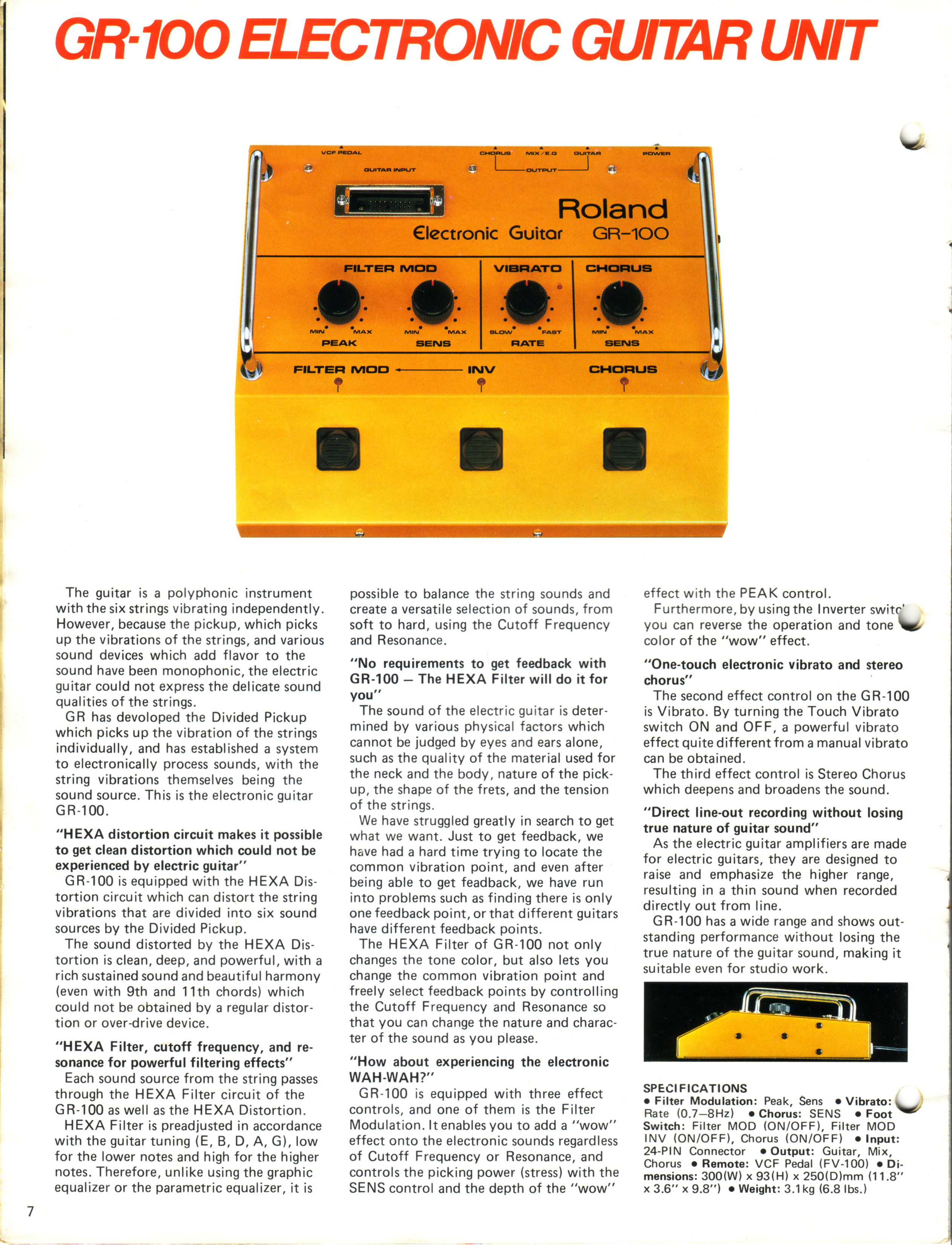
- Roland GR-100 Samples Sounds. The Roland GR-100 Owner's Manual has a list of "Factory Presets", Sample Sounds, at the end of the Owner's Manual. These sample sounds were intending to give some direction on how to use the GR-100, using features such as Filter Modulation, Chorus, and Vibrato, all served up with the classic hex fuzz sound the GR-100 is famous for. Check out this new YouTube video I posted which goes through the Sample Sounds to get a little flavor of what this vintage 'electronic guitar' synth sounded like!
-
SBC-1324 Roland 24 or 13 Pin Input to 13 and 24 Pin Output
Back in 2009 I was approached by a very talented Canadian guitarist who wanted to be able to control both vintage Roland 24 pin GR-series synthesizers and modern Roland 13 pin GK-series synthesizers with one guitar, either a 13 or 24 pin guitar.
The SBC-1324 is the unit I built to meet this need. The unit has both 13 and 24 pin inputs, and a master analog switch to select between the two. There are six amplifiers for each string input, used primarily to boost the 13 pin signals to the 24 pin format, but they can also be used individually to amplify any single string input, whether 13 or 24 pin.
-
Artist Highlight: Neal Schon
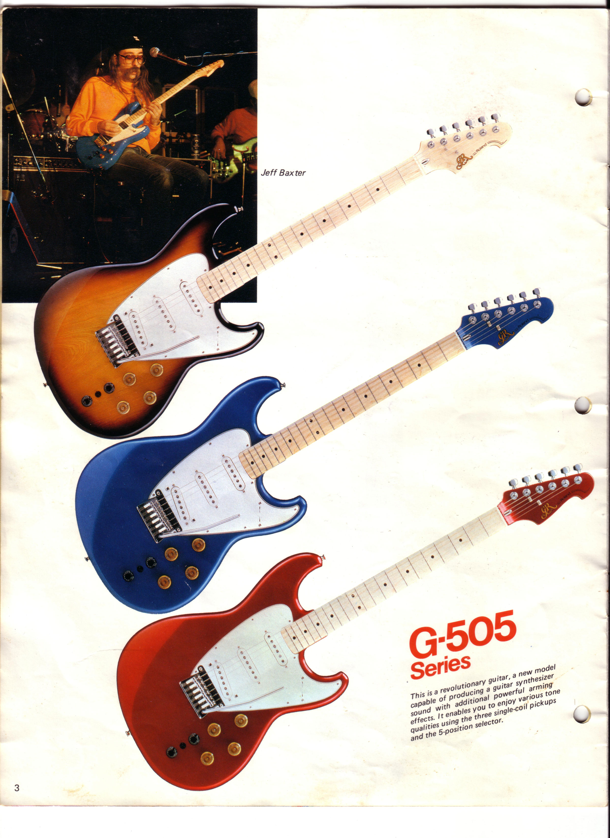
Journey guitarist Neal Schon was frequently seen in the early eighties playing a Roland G-505 guitar paired with the GR-300. Schon is not usually thought of as a 'Strat' player, much less a guitar synthesist, but he makes great use of the G-505/GR-300. An outstanding track is the tune 'Valley of the Kings', using the 'Duet' mode of the GR-300.
- Roland SIP-300 Fresh Photos! Super clean photos from an auction by Tone Tweakers.
- Roland GR-300 Emulation with Kontakt 5 or Roland SR-JV80-04 / SRX-04 Ultimate Keys / INTEGRA-7. Download a complete Kontakt 5 patch and trigger a GR-300 with MIDI! Or check out a demo of the Roland GR-300 patch created by the legendary Scott Summers.
- UX-20 - 13-Pin Splitter/Distributor with Buffered Guitar Input Schematic
- Pat Metheny writes about on using the NED Synclavier Digital Guitar Option - First Time Online! From the 1984 NED Owner's Manual.
- Steinberger XL2-GR Guitar Synthesizer Controller - Vintage Roland Ready Bass Guitar Synthesizer Controller
- Pedulla MVP-S Guitar Synthesizer Controller - The phantom Roland Ready Guitar Synth Controller!
- GK QuadBox Schematic Build your own GK QuadBox, 1 input, 4 output 13-pin Guitar Synth Signal Distributor - Combined US-20 and GKP-4 clone!
- RC-1324-VR Roland 13-in to 24-pin Converter Detailed schematic on the acclaimed RC-1324. Control vintage 24-pin Roland guitar synths like the GR-700 and GR-300 with modern 13-pin controllers like the GK-3, GK-2A or the Godin series of guitar controllers
- Modulus Graphite Blackknife Special Guitar Synthesizer Controller
- Roland GR-700 Operating System Upgrade New Sounds! Faster Response!!
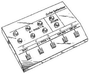
- Do-It-Yourself DIY Roland and Ibanez Guitar Synthesizer Control Panel Overlays
- The summer NAMM 1985 show was the year when MIDI became accepted as a standard across the industry, and guitar manufacturers unleased a variety of MIDI guitar products not seen since. From Roland to Steinberger to Ibanez to the ultra rare Octave-Plateau Voyetra MIDI guitar, MIDI was everywhere.
- Detailed information on the vintage IBM-PC music production software from Voyetra. Voyetra is the same company that produced the Kat and Kitten analog synthesiers, the ground-breaking Voyetra Eight polyphonic analog synthesizer, and the ultra rare Octave-Plateau Voyetra MIDI guitar.
- WBRA Public Television Music Video featuring Wayne Joness using Voyetra Sequencer Plus - Live Performance.
- Vintage Interview with Jazz Fusion pioneer John McLaughlin about using the Roland G-303 guitar synth controller and the New England Digital Synclavier with Digital Guitar Option
- Details on the amazing Synclavier II Digital Guitar
- East Side West Side by John McLaughlin From the Album Mahavishnu - Transcribed by Steve Vai.
- Vintage 1980 Full Page Roland G-808 Advertisement featuring Bernie Marsden (Whitesnake) - Who knew? Hard rock icon Bernie Marsden with a Roland G-808!
-
Gibson Custom Shop Les Paul "Studio Custom" Roland Ready Synthesizer Controller Update
More pictures on the Gibson Custom Shop Les Paul Roland Ready Synthesizer Controller page, plus an update on the number of models built. - Musico Resynator | Hexsynator - 1980s Pitch and Envelope Tracking Synthesizer with Roland 24-pin Guitar Synthesizer Input - Detailed photo gallery from November 2017 fundraiser at Sound City Studios in Van Nuys, CA.
-
Gibson Custom Shop Les Paul "Studio Custom" Roland Ready Synthesizer Controller
Beyond the standard Roland offerings in the G-X0X series, there are vintage 24-pin Roland-Ready guitars for just about every niche: the Hard Rock Hamer A7, the traditional player's Zion Strat, or the cutting edge Steinberger GL-2T/GR.
But the classic, eternal, "Cadillac" of the series has got to be the Limited Edition 1985 Gibson Custom Shop Les Paul with the Roland LPK-1 Electronics. Every guitar was the product of Gibson's acclaimed Custom Shop in Kalamazoo, Michigan. Kalamazoo made Gibson Les Pauls have been called the 'Holy Grail' of electric guitars. These vintage guitars combine all the craft and musicality with the feature-rich Roland LPK-1 electronics package, the same electronics found in the G-303 or G-808 guitars. - Jazz and the GR-50! Acclaimed Jazz Guitarist Brad Rabuchin rocks the Roland GR-50 in this track 39 Steps: A Spacewalk. This is Space Station MIR, a collaboration with Flugelhorn Horn genius and composer Michael Wetherwax, with Wayne Joness on keyboards and programming. Watch Now on YouTube.
- BX-13 Micro Schematics Yes! At long last! The final schematic for the BX-13 Micro is available on the website! This design incorporates a VCA (voltage controlled amplifier) with an option to select either guitar or hex fuzz as the guitar signal, plus using controller 2 (resonance) as secondary control source acting as a EV-5 pedal.
- At long last the Vintage Roland Guitar Synthesizer Resource site has a full profile on the Steinberger GL-2T/GR Guitar Synthesizer Controller, with unseen schematics, photos and video, with additional information on the GL-3T/GR and GL-4T/GR.
- Musico Resynator | Hexsynator - 1980s Pitch and Envelope Tracking Synthesizer with Roland 24-pin Guitar Synthesizer Input.
- Korg Z3 Patch Editor Adaption for the Korg Z3 - Thanks to Korg Z3 user David for this free software download.
- GS-500 Video Playlist featuring Terje Rypdal - Luc Bertels hipped me to videos of Terje Rypdal using the Roland GR-500 and GS-500.
- Roland GR-700 and GR-77B AB-700 Case - Image gallery with 12 photos of the rare official Roland factory road case.
- Xotica EA-1 with Roland Ready Guitar Graph Tech Ghost Pickups - Detailed information on this very rare, Rland ready 13-pin Acoustic/Electric Roland guitar synthesizer controller.
- Factory Blue Roland GS-500 - Last year while visiting Japan I stumbled upon a factory BLUE Roland GS-500 in a Tokyo music store! Check out the exclusive photos published for the first time.
- Sounds of the GR-77B! New video posted featuring a layered bass combination of the Roland MKS-70 (same sound engine as the GR-77B) and the GR-77B.
- Pat Metheny Extended Interview - I tracked down the original Guitarist Magazine, May 1985, and have posted the complete interview with Pat Metheny. The previous interview was an abbreviated version.
- GR-300 Synthcheck - A detailed 2000 word review from "The Complete Music Magazine", dated November 1980
- Gibson Explorer - Finally! A home for one of the rarer custom Gibson vintage Roland guitar synth controllers
- Jimmy Page - Vintage 1985 magazine ad featuring the guitar legend and his G-707/GR-700 rig!
- LPK-1 Installation Diagram thanks to John Doucette for emailing the scans.
- GK-20 Schematic - 13-pin Guitar Switcher, Schematic ready for download
- Filter/Buffer Schematic - Schematic ready for download.
- Roland GR-700 and GR-77B Updates: From the Roland User Group Archives, a complete MIDI guitar and MIDI bass system profile!
- Roland GR-77B Updates: Finally! The Roland GR-77B and G-77 pages have been updated. Be sure to check out the G-77 page as well.
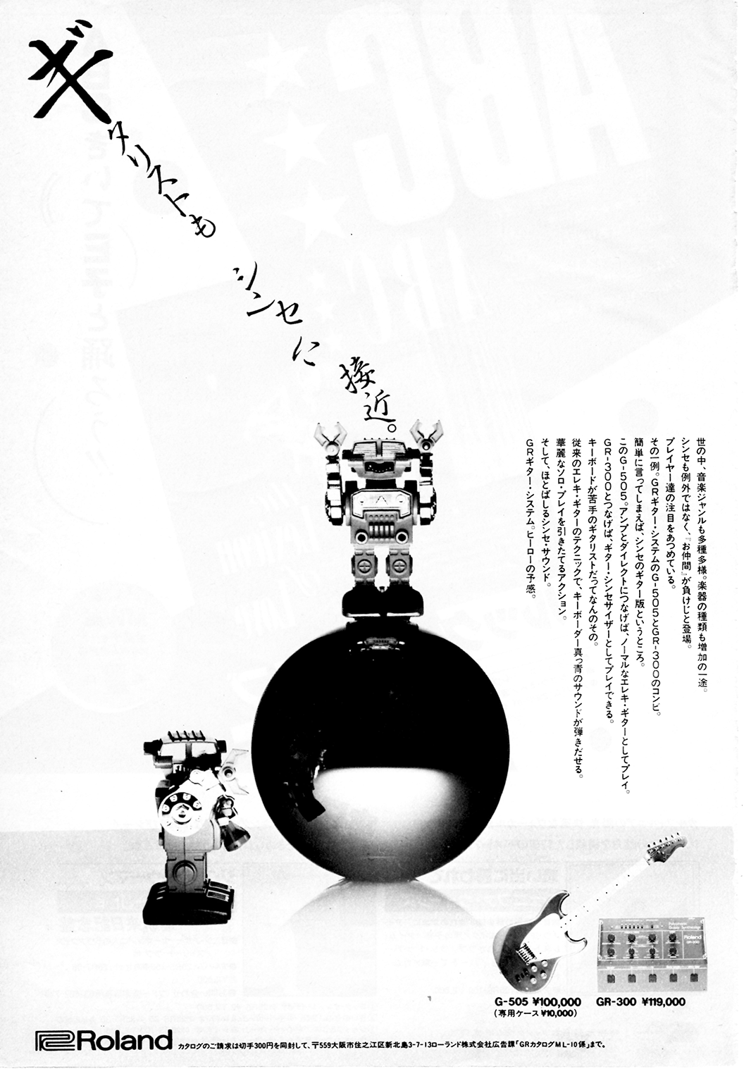
- Vintage Roland G-505 and GR-300 combination magazine advertisement.
- GR-700 One Step Beyond!: From the 1985 Roland User Group Magazine
- GR-700 4x Memory Expansion!: Easy to do, super DIY Memory Expansion!
- Ibanez IMG2010 and MC1: Updated! High-Res Brochure from 1985
- G-707 Steve Hunter: Vintage Product Review from 1985, Part 2!
- G-707 Steve Hunter: Vintage Product Review from 1985, Part 1
- GR-500 Steve Hackett: Vintage Product Review from 1978!
- GR-500 Patch Sheet: Original Blank Patch Sheet
- GR-500 - Solo Voice Tuning : Adendum on Tuning the Solo Section
- GR-300 Filter Mod: LFO to Filter Modification
- GR-300 Output Mod: Increase the output of your GR-300!
- GR-55 Schematics, Service Notes: Full factory service notes for the Roland GR-55
- Ibanez MIU8: Specs, photos, details on the rarest of rare!
- MIU8 Schematics: Schematics and Service Manual (pdf)!
- Korg Z3 Product Page: From early Product catalog!
- Hamer A7 Guitar: Added to the guitar pages, a tribute to the Hamer Phantom A7! Tubo Lover rocks!
- GR-500 24-pin Connector Change: Documentation of the change from the original, pin-type C24 connector to the much more common C24 positive (locking frame) connector.
Features and Specifications
Introduction
The Pat Metheny Sound
Links
Versions
Photos
Videos
Modern Alternatives
Modifications: Three Simple Mods
Modifications: Routing LFO to Filter or Pitch
Modifications: Increasing GR-300 Output
Remote Control Pedal
Schematics - Repairs
Accessories
Foot switches
DIY Foot switches
Filter Pedal
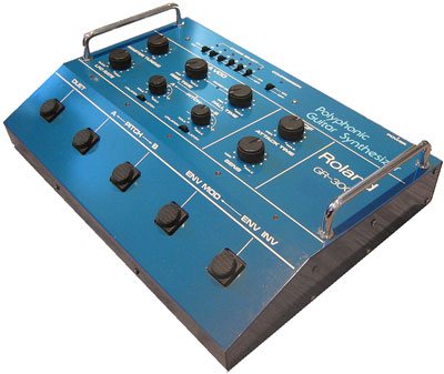
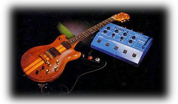
DIY Remote Control Box Japanese Brochure
1981 Greco Catalog
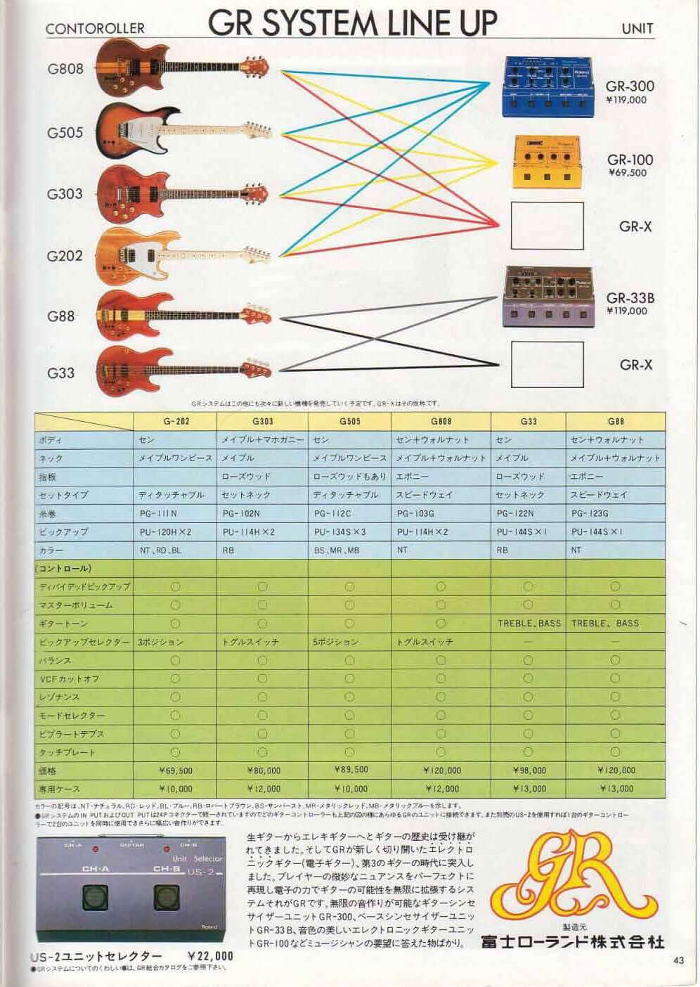
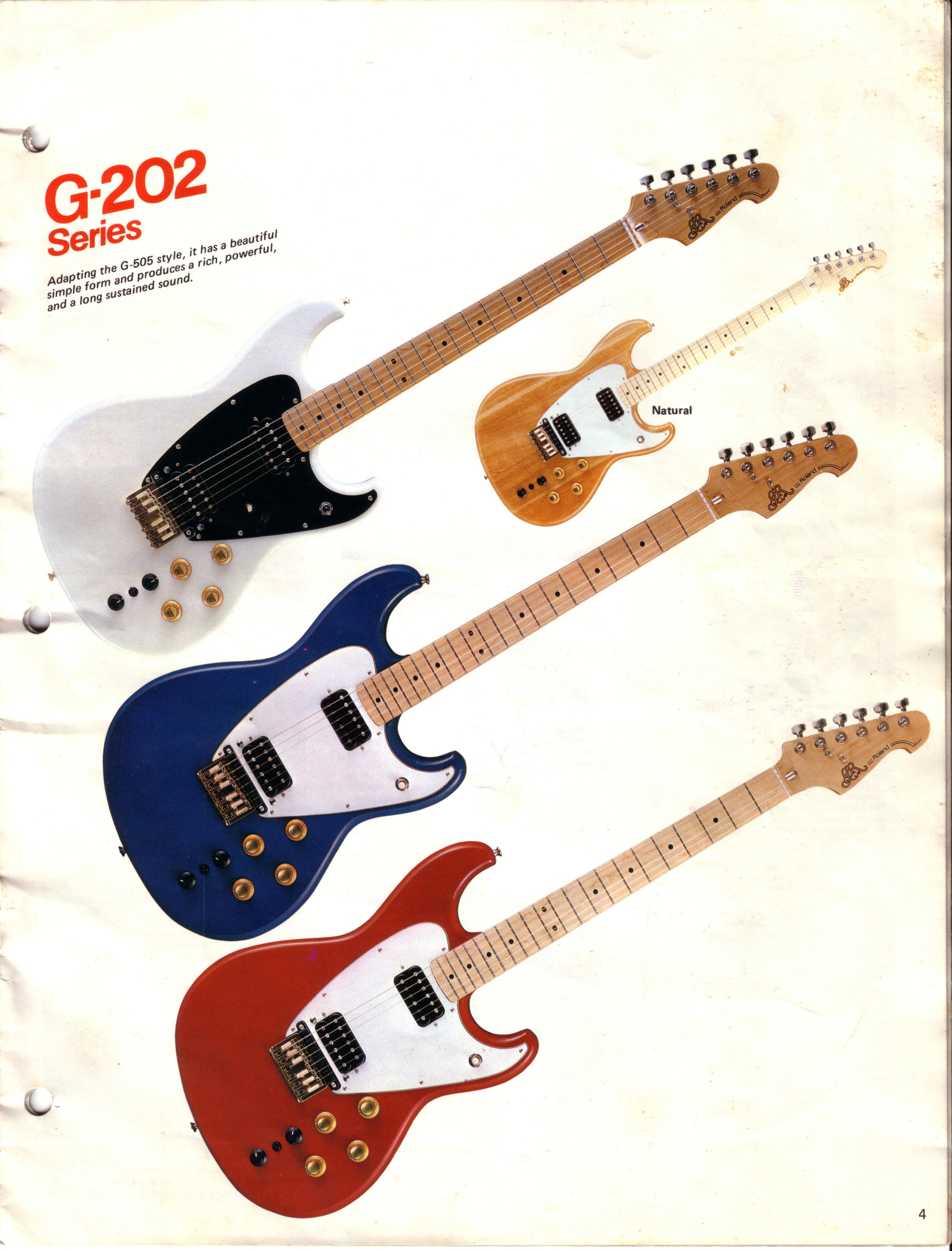
1982 Roland Brochure
1984 Roland Brochure
Advertising
UK Magazines
How the GR-300 Works
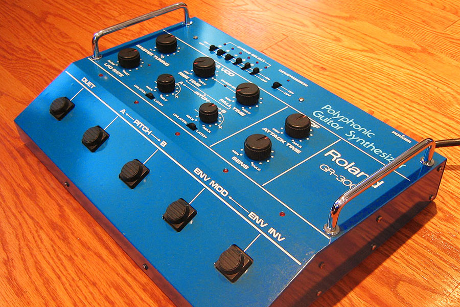
Roland GR-300 Analog Guitar Synthesizer
Features and Specifications:
- 6-voice polyphony
- 2 oscillators per voice
- VCOs (voltage controlled oscillator) are directly harmonically locked to each string, but can be tuned separately
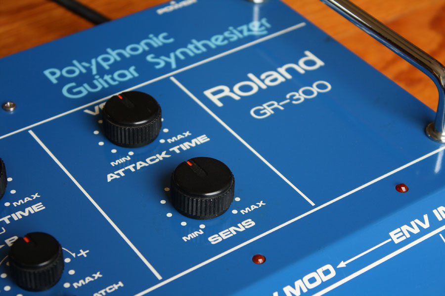
- VCF (voltage controlled filter, low pass) -24 dB per octave, with envelope modulation (attack and sensitivity)
- Low Frequency Oscillator, for Vibrato Effects
- Built-in foot switch controls the VCO mode (single/dual), VCO harmonize pitch (detuning of the VCO's), and VCF mode (on, bypass, or inverted)
- Pedal control input for the VCF
- The GR-300 can output either the guitar, the synth, or a mix of the two
- Synchronized, flashing LED status indicators
- Dimensions: 15.7" (W) 11.4" (D) 3.9" (H)
- Power Requirements: 20 watts
- Response Time: 3.32 ms
 |
|
Roland G-808, GR-300 and FS-3
|
Introduction to the Roland GR-300:
At the end of the 1970s, Roland Corporation introduced the world to the GR-300 analog guitar synthesizer. While there have been numerous advancements in music technology since then, the GR-300 remains the pinnacle of analog guitar synthesis. Although the sound palette of the GR-300 is very limited, the GR-300 has the fastest, most accurate tracking ever developed. Unlike much of guitar-to-MIDI pitch recognition technology, the GR-300 guitar synthesizer does not require the player to adapt technique to get astonishing results. It is not that the GR-300 ignores fret board misfires, or translates them into wildly inaccurate notes as some MIDI systems will. The GR-300 instead creates a unique analog synth equivalent. For example, the initial atonal pick attack is converted into a sound very reminiscent of the "spit" sound heard at the beginning of a trumpet phrase.
 |
|
Roland GR-300, G-808, and G-303
|
The trumpet comparison continues: the GR-300 has a waveform very similar to a sawtooth, with a brassy, aggressive tone. But the GR-300 waveform does something unique: it changes shape as the player moves up the fret board. An "E" played one octave above an open "E" string will not only be sounding at twice the frequency, but the harmonic content will be very different as well. This is the happy consequence of the brute force synthesis used in the GR-300. Inside the GR-300, the amplitude (volume) of each note is related to its pitch. The low "E" will have twice the amplitude of an "E" one octave above. Similarly, the high open "E" string, two octaves above the low "E" string, will have one quarter the amplitude of the low "E". To eliminate this volume difference, Roland used a "chopper-gate" circuit to basically crop the top of the waveforms. The higher notes look more like a classic sawtooth waveform, while lower notes have a more rounded tone. The result is a rich, complex sound where every note played on the guitar across the instrument will have an individual sound. An unfortunate consequence of this design is that higher notes will have less sustain than lower ones.
Duplicating the "Pat Metheny" GR-300 Sound:
Pat's settings are dead simple, he does not use any of the modulations, etc. on the GR-300. Just set the filter cutoff to 85% - 90%, and add about 10% resonance on the guitar. The sound should be a little dark. His solos always start that way.
You want to program pitch "A" to one octave. When you engage pitch "A" the sound jumps one octave, but it also gets brighter and changes in tone.
These two notes have the same pitch in the GR-300:
- High E string, fret 12 (no pitch shift)
- High E string, open, (pitch shift up one octave)
However, the second one (with the pitch shift) is brighter. Watch any Pat solo, and usually before the last chorus, you can see him lean into a foot pedal. That is him hitting the "pitch A" foot switch, set to one octave.
Also, his live GR-300 sound is not the same as the recorded sound! The recorded is cleaner, and easier to copy. The recorded tone comes across as pure GR-300, but his live sound is little more overdriven, perhaps a combination of his amp and cabinet configuration
If you want to nail the Pat Metheny GR-300 tone, it may be easier to start by studying a studio recording.
But...the real key to sounding like Pat is copying his phrasing. So much more difficult than turning a knob, but his choice of when to pick, or when to slide or hammer on to a new pitch, effects the sound of the GR-300.
 |
|
Pat Metheny with Roland GR-300 and G-303
|
The GR-300 has two oscillators, both harmonically locked to the string pitch, but one oscillator can be offset by a range of plus or minus one octave. So it is possible to play one oscillator an octave below pitch, or to layer two oscillators together at the interval of a perfect fifth. These pitch intervals can be preset as pitch offset "A" and "B." There is also an adjustable pitch rise and fall time, to create a portamento/glide effect. The -24 db per octave low-pass filter in the GR-300 also tracks pitch, so as pitch preset "A" or "B" are engaged, the filter will also change. Higher pitches open the filter more, making for a brighter sound. For more than 30 years, guitarist Pat Metheny has been thrilling audiences with his GR-300 solos. Pat will often engage the pitch offset to lift the end of his solos one octave up. Not only does this raise the pitch, but it also opens the filter up more, making for a brighter sound. The GR-300 includes a LFO vibrato circuit, and basic filter envelope modulation. There are controls for filter attack time and sensitivity, and the filter modulation can be inverted as well.
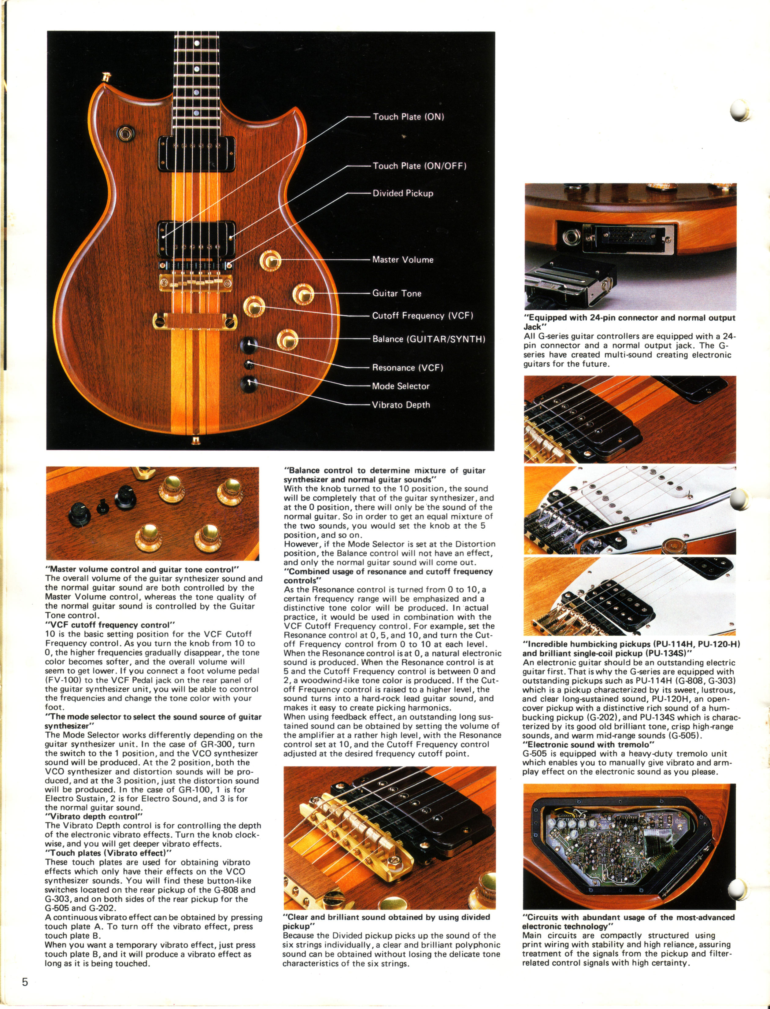
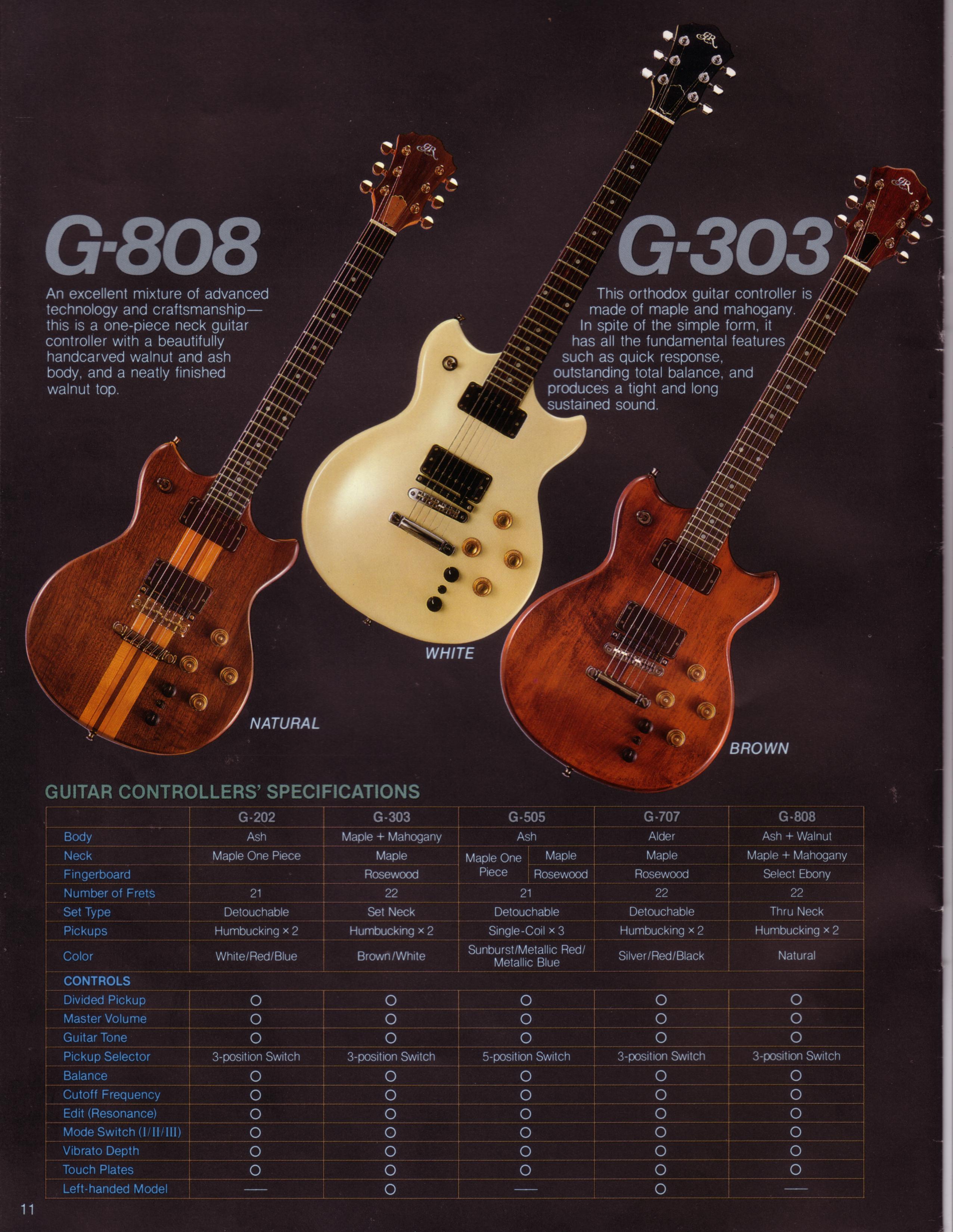
The original G-202/303/505/808 guitars have a hexaphonic fuzz circuit, and the GR-300 is the only Roland guitar synthesizer to access this sound. With the GR-300, players can play either the hexaphonic fuzz, the VCO synth sound, or both of these sounds combined.
|
|
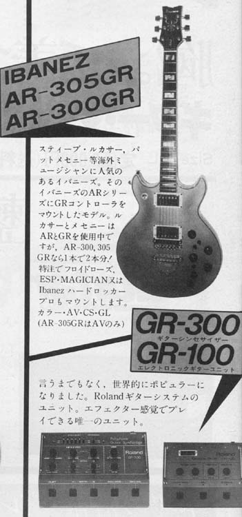
| The Ibanez AR300GR and AR305GR, vintage Roland-Ready guitars. Click on either image to enlarge. | |
The GR-300 has maintained a unique level of recognition thanks in large part to musical genius of Pat Metheny. Guitar players who see Pat play for the first time want to know how to get "that sound." While Pat has continued to embrace new guitar technology, he has maintained a close relationship with his G-303/GR-300 combination. Pat has demonstrated with the ease of a virtuoso just how expressive a guitar synthesizer can be. For players used to working with the kludgey, unforgiving MIDI synthesizer systems, the GR-300 is a refreshing, responsive system.
Unfortunately, as mentioned before, the GR-300 does have a very limited sound palette, and it can be difficult to use the GR-300 in a way that does not invoke Pat Metheny. Other guitar players who championed the GR-300 in their careers include Andy Summers of The Police, who tended to use the unit as a source of pads, or dark, swelling tones. This can be heard on the break of "Don't Stand so Close to Me". And Robert Fripp and Adrian Belew of King Crimson used the GR-300 extensive in the early 80s, most notably on their stunning album "Discipline." The lead distinctive synth sound heard at the beginning of "The Sheltering Sky" is a GR-300.
Links to more information:
- Premier Guitar Magazine article comparing the original GR-300 with the emulation in the VG-99, by Wayne Scott Joness
- Premier Guitar Magazine article comparing the original GR-33B with the emulation in the VB-88, by Wayne Scott Joness
- Vintage Guitarist Magazine Interview with Pat Metheny highlighting the Roland G-303/GR-300.
- 1980 Roland Product Information on the Roland GR-300, G-303 and G-808.
- 1980 Roland Product Brochure on the Roland GR-300, G-303 and G-808.
- GR-300 Synthcheck - A detailed 2000 word review from "The Complete Music Magazine", dated November 1980
- Mix Magazine article detailed recording "Every Breath You Take" and Andy Summers' vintage Roland GR-100, GR-300 and US-2 rig.
- Sound-On-Sound Magazine article detailed the history of Roland Corporation during the 1980s.
- Electronics & Music Maker Magazine GR-300 Review, November 1981
- Download the GR-300 Owner's Manual
Version History A - B - C:
|
|
|
|
|
|
|
|
|
|
|
|
|
Click on image to enlarge
|
|
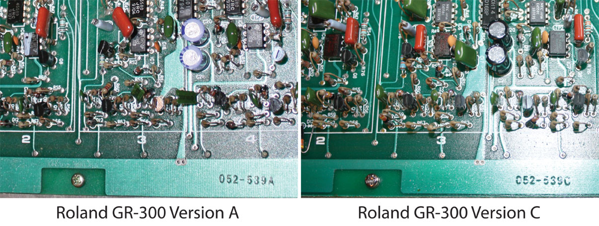
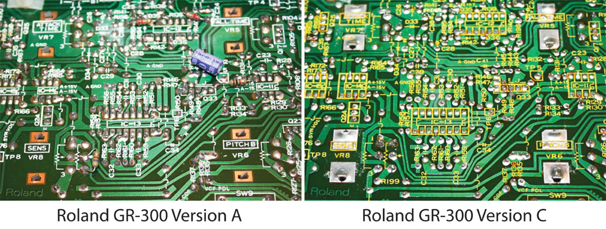
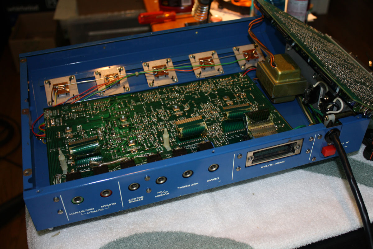
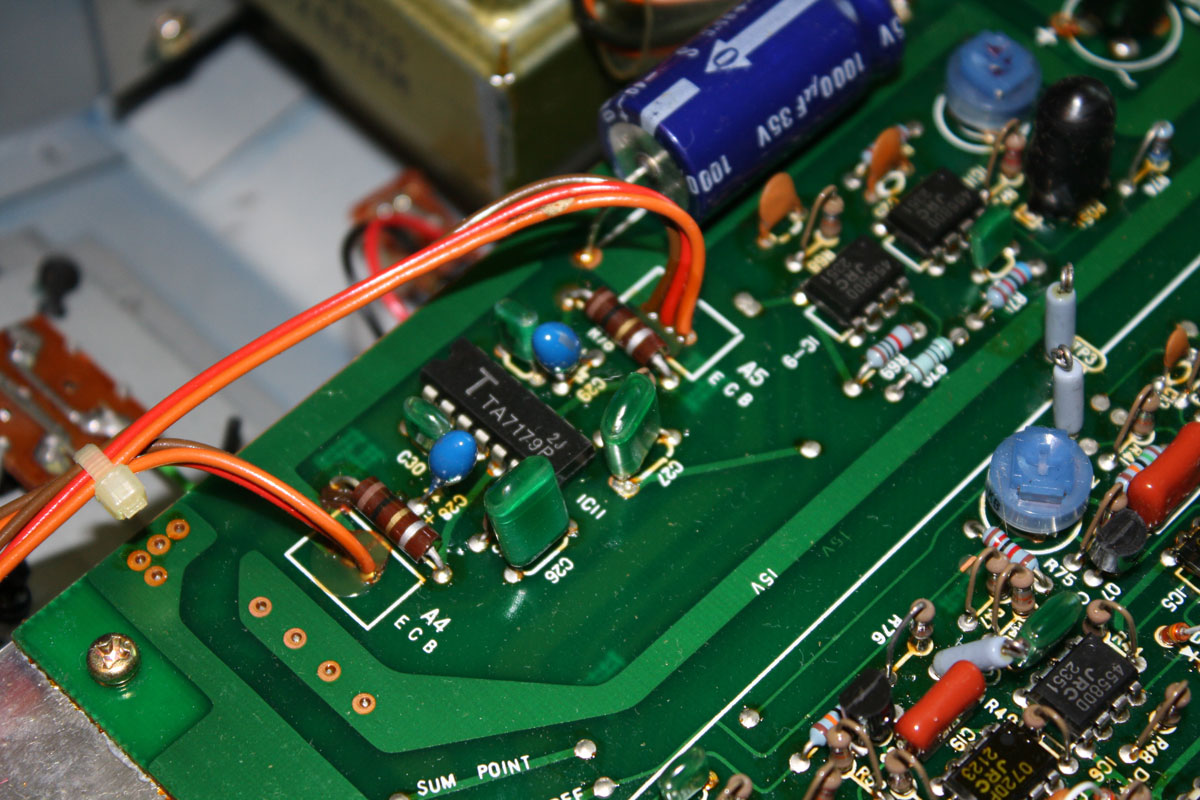
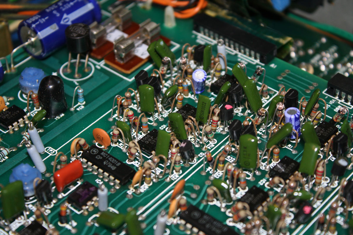
There are three versions of the Roland GR-300. These are distinguished by the letters "A", "B" or "C" appended to the part number printed on the top voice board. The only way to know which version you have is to remove the bottom panel, and look at the printing in the lower right-hand corner of the voice board. You will see either 052-539A, 52-539B, or 52-539C.
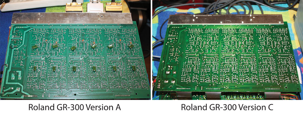
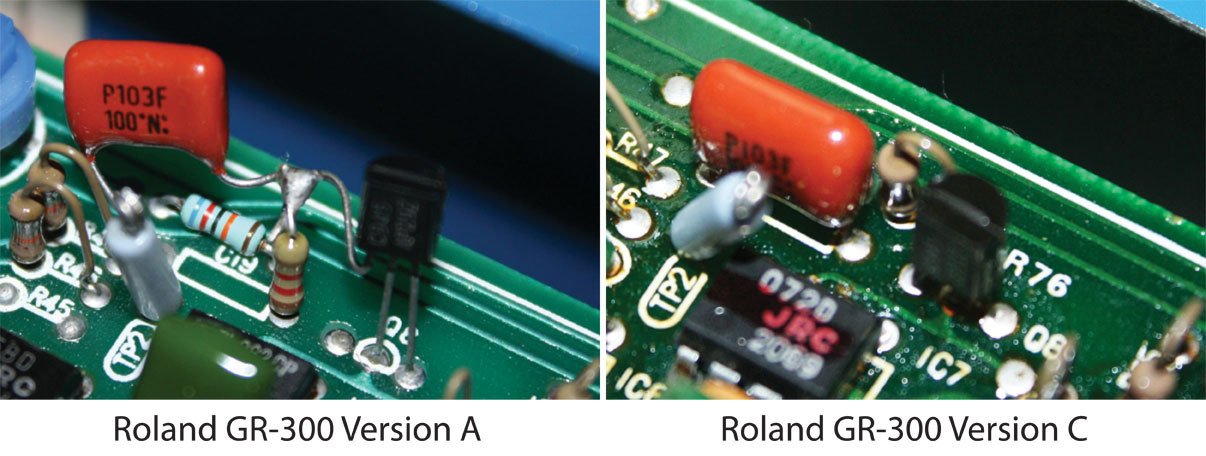
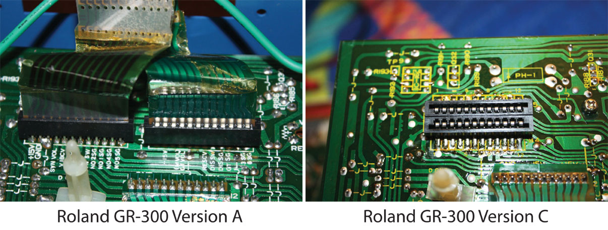
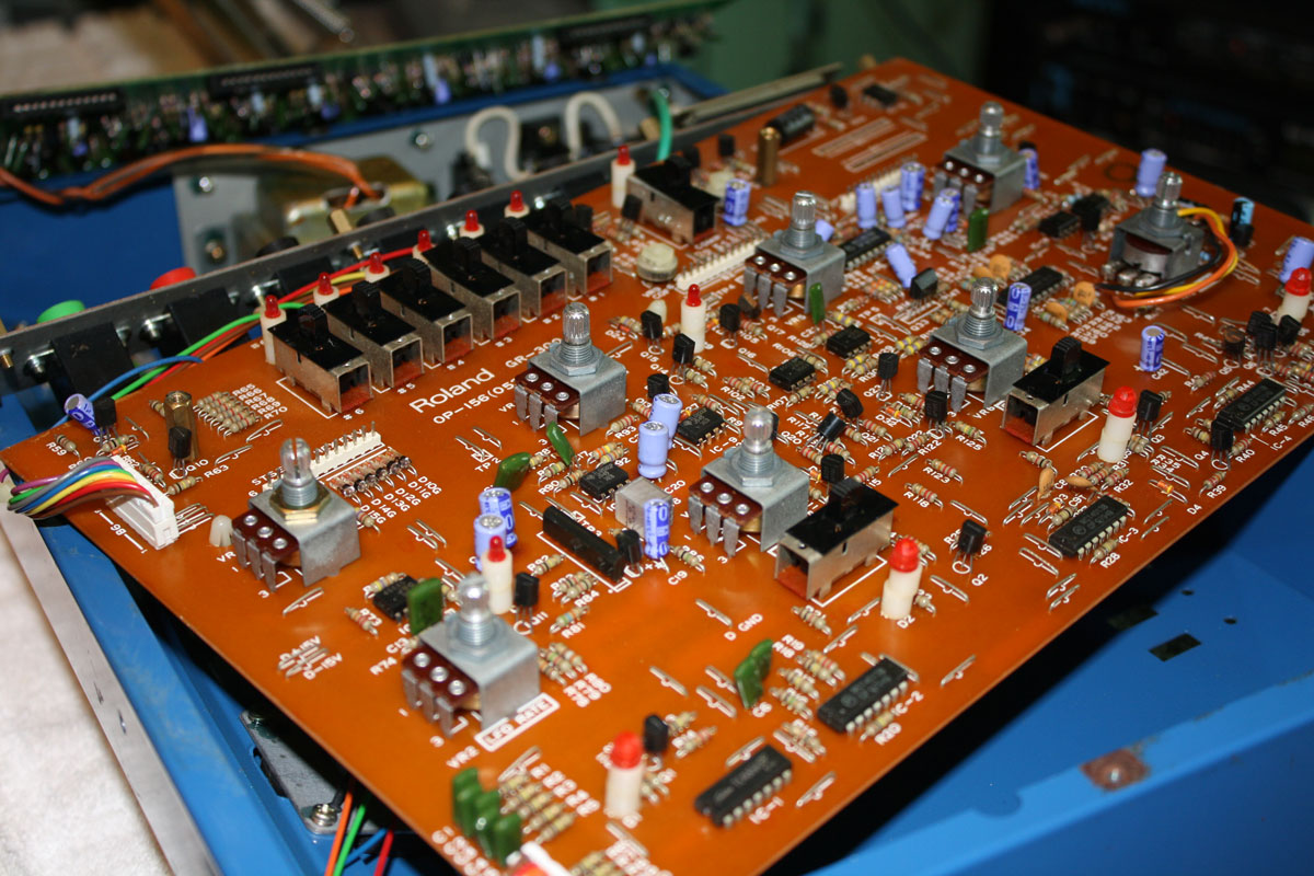
Of the three versions, "C" is the most common, and the most desirable. Electronically and functionally, these GR-300s are the same. However, version "C" is the version referred to in the well-documented Roland GR-300 service manual. Version "A" is notable for the fact that many components are found tack soldered onto the circuit board. Apparently when the circuit board was produced, some components were left off the circuit board, and so capacitors, transistors, etc. were soldered to existing components to complete the circuit. Also, there is a small network of resistors added to the power supply, not documented in the service manual, and not included in the more common version "B" and "C". The final curiosity are the two, 12 pin ribbon connectors. In all other Roland products, the two 12-pin connectors are positioned parallel, side-by-side. This configuration is in line with the way the ribbon connects to the 24-pin cable connectors. However, on the version "A" synth, the two 12-pin connectors are in series, which makes it more difficult to connect the ribbon to them. There is a companion Roland G-303 guitar, version "A" as well. Like the version "A" GR-300, the version "A" G-303/808 electronics have the ribbon connector position in line. And the circuit board layout for the version "A" guitar is similarly different from the published documentation in the service manual.
One final note: when I first found the Anderton GR-300 modifications, which inspired me to create this website, I was unable to follow Craig's directions on locating the parts on the GR-300 circuit board. It was not until many years later, when I saw my first revision "A" board, that I realized that Craig's plans were referencing the earlier, rare version "A" board, and not the version "C" board in my possession.
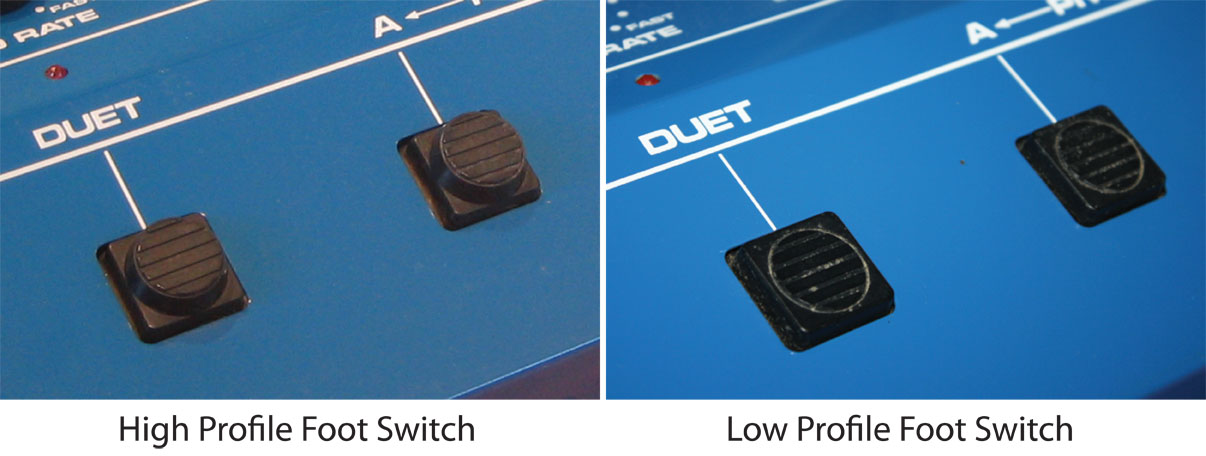
Foot switches: there are two versions of foot switches found on the GR-300. The most common foot switch is the larger, chunky rubber foot switch. This is the same part used on the Roland GR-100, GR-33B and US-2. Some GR-300s have a lower profile foot switch made of harder rubber. I have not been able to make a clear correlation between production date, and the use of these different foot switches, though it appears more common to find the lower profile switch in the later, revision "C" GR-300s. I will note that the actual switch mechanism used in these foot switches underneath the rubber cover is the same in both designs, and it is the same switch used in the Roland GR-700.


Three Simple GR-300 Modifications
Click here to learn about Craig Anderton's classic Three Simple GR-300 modificatioons.
Check out the original GR-300 modifications that started this website! Many thanks to Dempsey Elks who dug through his Guitar Player archives, and emailed me the original Craig Anderton GR-300 article.
- Improving hex fuzz high-frequency response
- Separate hex fuzz outr
- Vibrato pedal

Modification: Routing LFO Modulation to Filter and Pitch
Click here to learn how to easily modify your GR-300 to use the LFO to modulate the filter.
- Use LFO (low frequency oscillator) to modulate both the pitch (normal GR-300 operation) and Filter Cutoff (modification)
- Enables multiple target modulation (both Pitch and Filter Cutoff) similar to standard Analog Synthesizer
- The parts required are readily available: resistors, small capacitor and basic operation amplifier (TL072).
Modification: Increased Output
Click here to learn how to easily modify your GR-300 to increase the output and lowerthe noise floor.
- +12 dB more output
- More dynamic range
- Less noise
- More sustain
- Better guitar-to-synthesizer balance
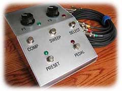
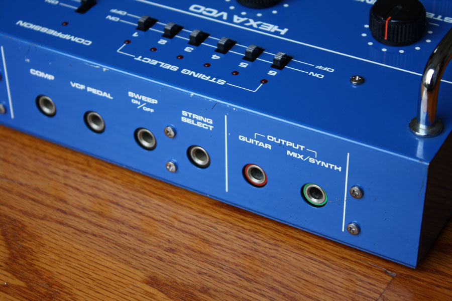
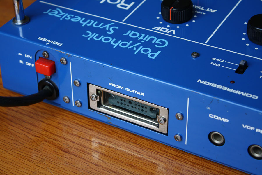
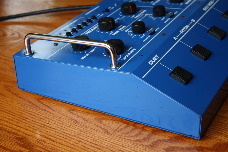
GR-300 Remote Control Pedal
Click here to learn how to build your own GR-300 Remote Control.
- 2 Filter Presets
- Filter Pedal Control Option
- Pitch Sweep On/Off
- Compression Of/Off
- String Select On/Off
Accessories:
 |
 |
|
CB-300 Carrying Case
|
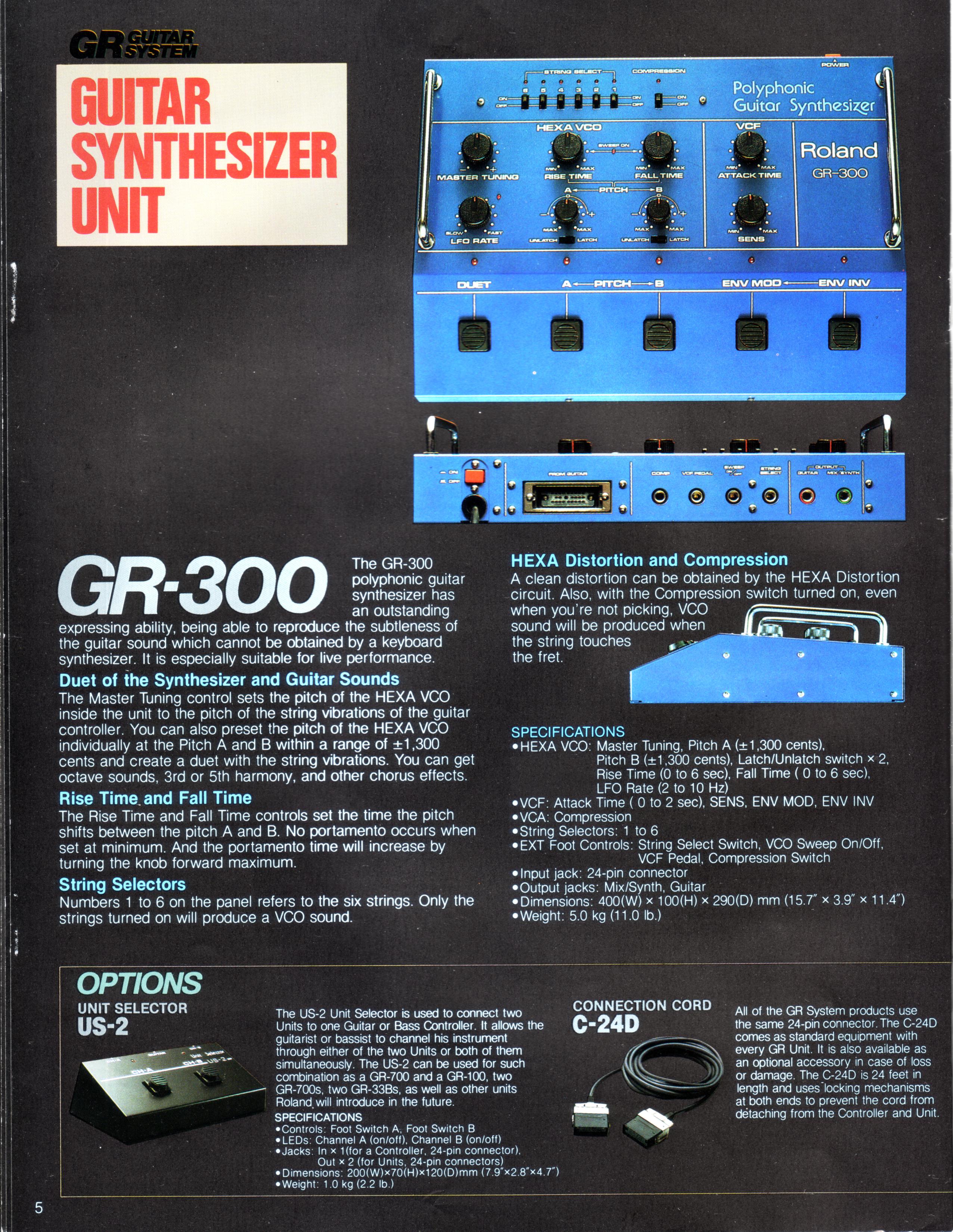
Page six of the 1984 Roland GR series brochure lists several options and accessories for the GR-100, GR-300 and GR-700.
FS-1, FS-2 and FS-3 Foot switches: The foot switches worked with the GR-300 to control compression, pitch sweep, and string select. The GR-33B also has a string select foot switch input.
FV-200 volume pedal: The FV-200 volume pedal could be used to control the filter cutoff on all the vintage Roland synths, GR-100, GR-300, GR-33B and the GR-700. The FV-200 could also be used as a pitch pedal with the Roland GR-700. The both the Roland GR-100 and GR-300 owner's manual list the FV-20 volume pedal for use with the GR-300.
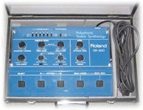
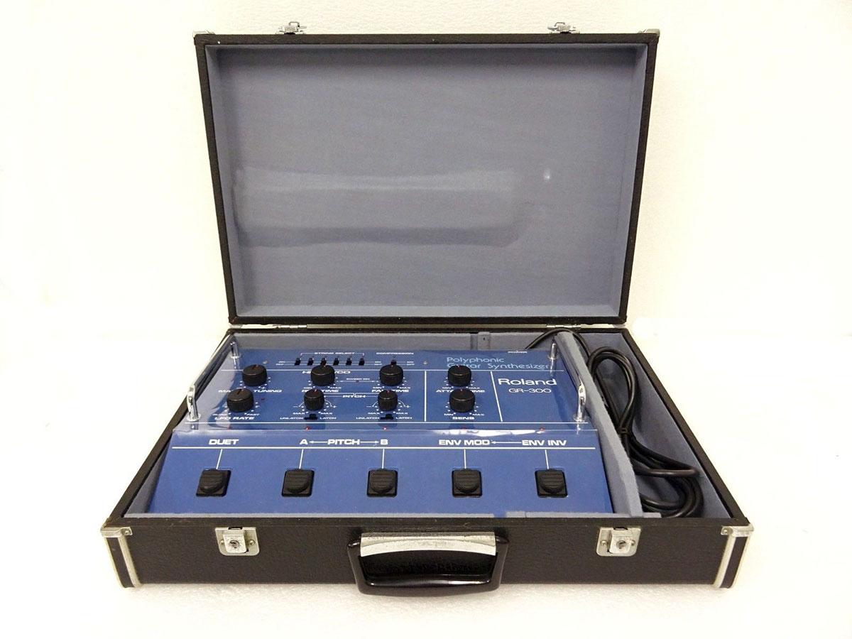
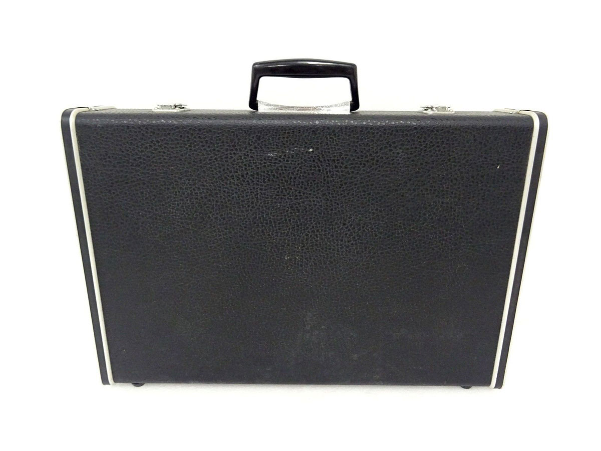
CB-300 case: The rarest of all vintage accessories, Roland made a leatherette case for the Roland GR-100, GR-300 and GR-33B.
And page five lists the Roland US-2 Unit Selector and the C-24D connecting cable.
Most of these accessories are impossible to find now, but there are modern equivalents that you can use to expand the playing experience with the vintage Roland GR-300.
Original Roland GR-300 Case
|
|
|
|---|---|---|
| Click on any image for larger view. | ||
Foot switches:
|
|
|
|
Roland FS-3 Foot switch
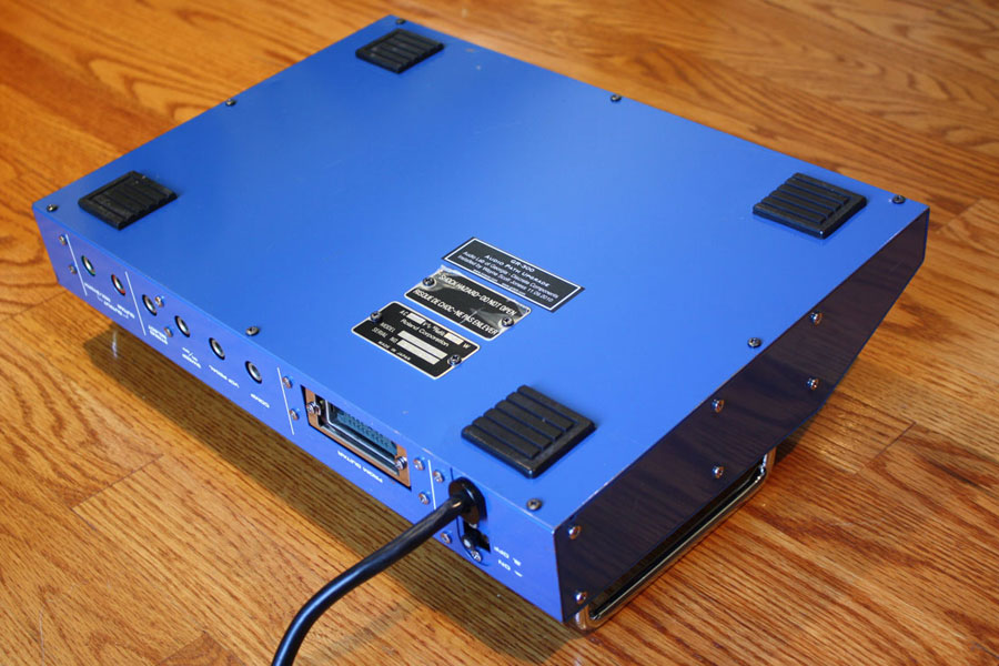
|
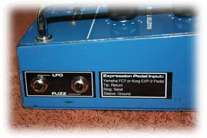
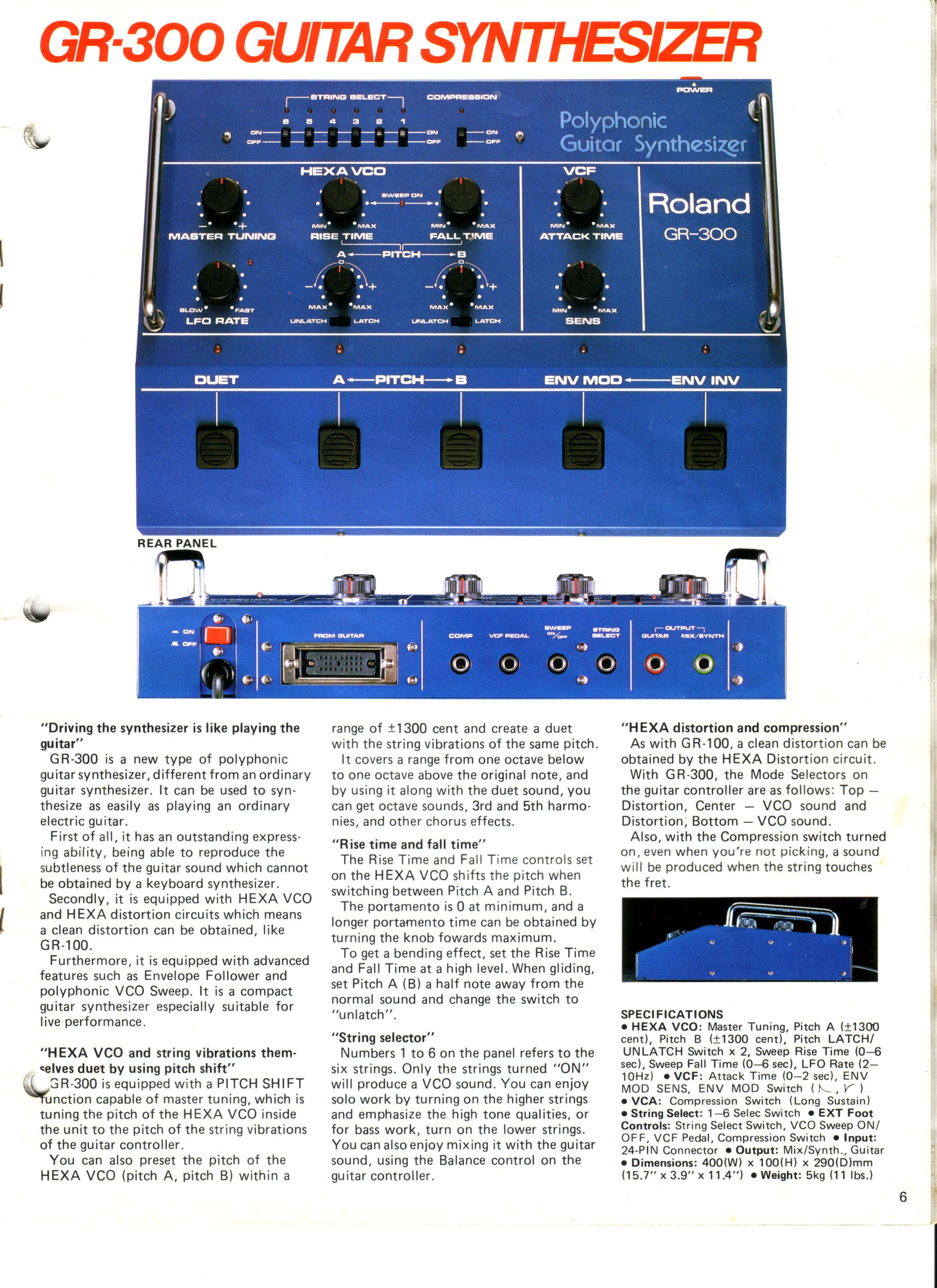
GR-300 Rear Panel Switch Inputs
|
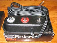
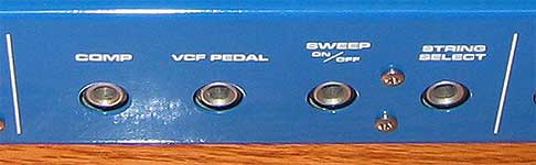
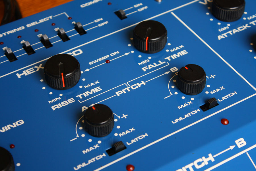
The early Roland GR-300 brochures often picture the GR-300 with the Roland FS-3 foot switch. The FS-3 is just three independent foot switches in a single enclosure. This is a perfect match for the GR-300, since the GR-300 has three connections on the back for foot switches: compression, pitch sweep, and string select. The switches all work a little differently. For example, the compression feature also has a top panel switch to turn compression on or off, with a status LED as well. Plugging a foot switch into the rear panel compression jack defeats the top panel switch.
As for pitch sweep, this feature is always on. As a result, most GR-300s have the "rise time" and "fall time" knobs turned all the way counterclockwise to a setting of zero. The pitch sweep feature also has a status LED. Notice that it is always on! Plugging a foot switch into the rear panel sweep jack lets you turn this feature on or off.
Finally, there is the string select jack on the back. String select only works in mode 3, the "synthesizer only" mode. This is the mode the GR-300 is in when the switch on the guitar is in the "up" position. In mode 3, you can individually turn strings on or off using the six string select switches on the top panel. There is no dedicated status LED for string select, like there is for compression or sweep, but if you have a string switched off with the top panel switches, the associated LED will not light when the string is played. I have to admit that a few times I thought I had a problem with my GR-300, only to notice I had inadvertently switch a string off!
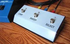
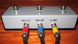
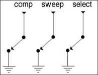
Do-It-Yourself GR-300 Foot switch:
It is quite easy to make your own GR-300 foot switch. Grab a box, drill three holes for foot switches and three holes for input jacks, and you are set! Wire the switching terminals to the sleeve and tip connections on the output jack. I picked up a junked foot switch at a used gear shop, sanded it down and gave it a coat of primer, and used to transfer lettering to label the switches. Several coats of clear coat were added to protect the lettering.
 |
 |
 |
Filter Pedal:
 One of the best features of the Roland GR-300 is the excellent -24 dB per octave filter. This filter gives the GR-300 much of its character, and it sounds about as good as any analog filter I have ever heard. In addition to the dramatic sweep of a -24 dB per octave filter, the GR-300 is also capable of high levels of self-resonance. It is also very easy to expand on the range and power of the filter on the GR-300. On the rear of the GR-300 is a filter pedal input. You can plug any volume pedal into this jack, and easily sweep the filter. Some pedals work better than others, depending on your musical requirements.
The filter pedal input works by moderating a control voltage that is summed in the Voltage Controlled Filter circuit. The greater the resistance, the greater the range of the sweep of the filter. A typical volume pedal has a 10K potentiometer. A typical CV pedal uses a 50K potentiometer, and there are some pedals with 100K potentiometers. As you can tell by listening to the samples below, the higher the value of the potentiometer in the pedal, the greater the filter effects.
Also, the filter pedal input works in conjunction with the filter knob on the guitar. The filter knob setting on the guitar sets a "base line" that the filter sweeps from. With the knob on the guitar set to "zero," the filter pedal will sweep from a very dark sound to a brighter tone. With the filter knob on the guitar set to "5," the filter pedal will start with an open sound, and then sweep to an even brighter sound than is possible with the guitar alone. This is an important point: you can actually extend the range of the filter on the GR-300 by adding a filter pedal. If you want really bright, screaming synth tones, or dangerously loud resonance levels, adding a filter pedal gives more range to the GR-300. If you are using a volume pedal, you will plug a standard guitar cable from the GR-300 filter pedal jack to the output of the volume pedal. The GR-300 will then measure the amount of resistance from the wiper to the ground terminal. Similarly, with a Roland FV-50L Pedal, you will plug a standard guitar cable from the GR-300 filter pedal jack to output of the FV-50L. Again, the GR-300 will then measure the amount of resistance from the wiper to the ground terminal.
Audio Samples:
| Value | Sample |
|---|---|
 |
|
 |
|
 |
I recorded these audio samples with a 10K, 50K and 100K potentiometer, and maximum resonance. Also, the sweeps were done with the initial guitar filter setting of 0 (minimum filter). You can hear in all these examples how the external filter pedal expands the range of the filter. Notice how the 10K pedal does not move the filter frequency very much. The 100K really opens the filter up, but it does so too quickly. There does not seem to be any effect once the filter is open, so about half of the travel of the pedal is useless. The 50K pedal seems to be the "just right" value. It does not get quite as bright as the 100K, but overall the range is useful and effective.
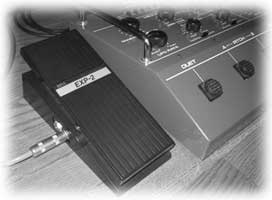
GR-300 Filter Pedal Recommendations - Yamaha FC-7 or Korg EXP-2
As you can see this is a bit of a toss-up. The Yamaha FC-7 requires a little wiring trick to get the pedal to work as expected. It works, but it would be backwards, with the filter open when the pedal is back, and dark with the pedal is closed. To reverse the operation of the FC-7 I wired two TRS 1/4" jacks together, but swapped the tip and ring connection. But major plus is the very long travel of the FC-7 pedal, much like a traditional pipe organ pedal. This makes it so much easier to control the sweep.
My other favorite pedal is the flexible, versatile Korg EXP-2. With a Korg EXP-2, you do not have to re-wire the pedal, since it also doubles as a volume pedal. Just plug a standard guitar cable from the GR-300 filter pedal jack to the output of the EXP-2 volume pedal jack, and you will get a wide, musical range of filter sweeps.
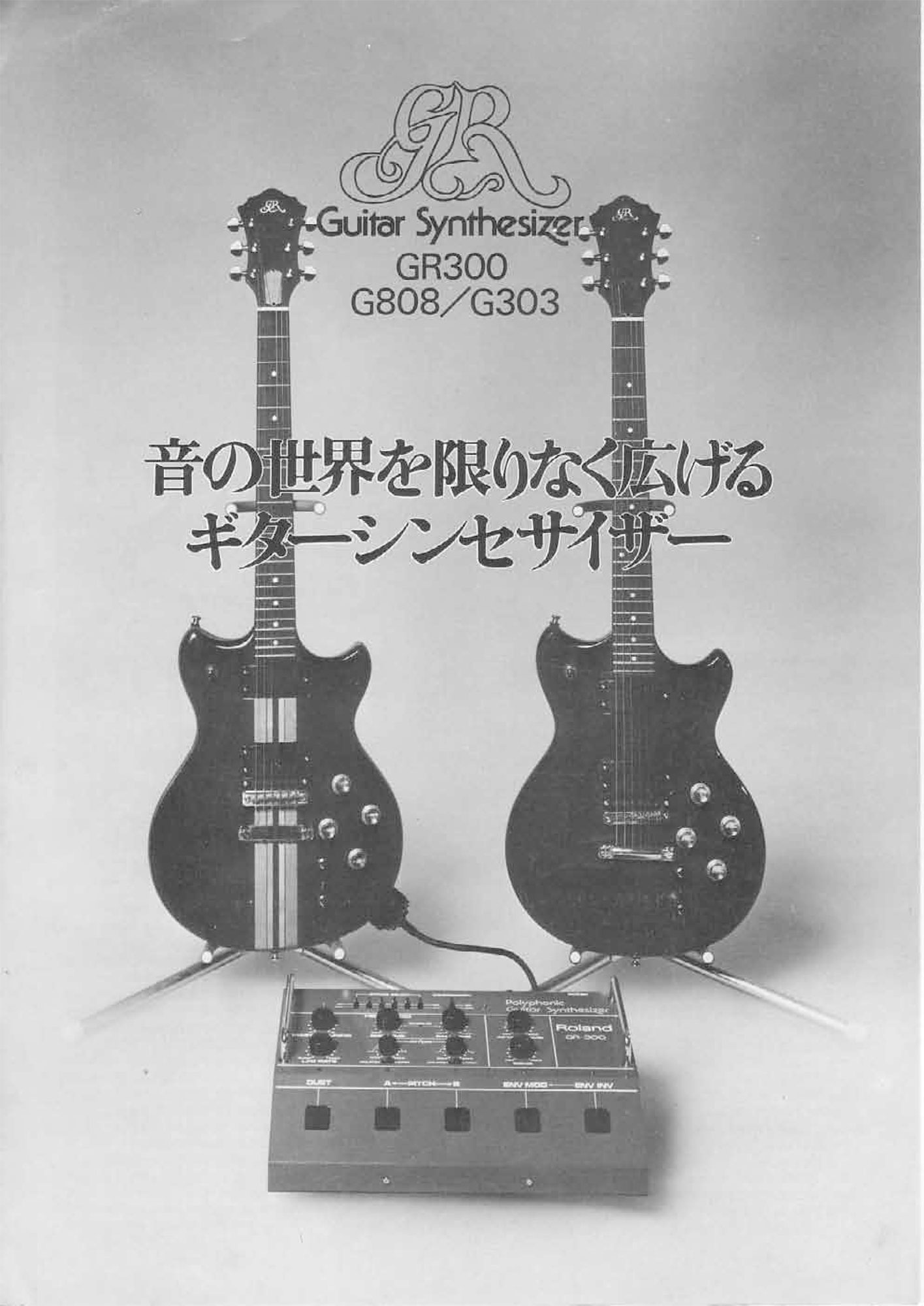
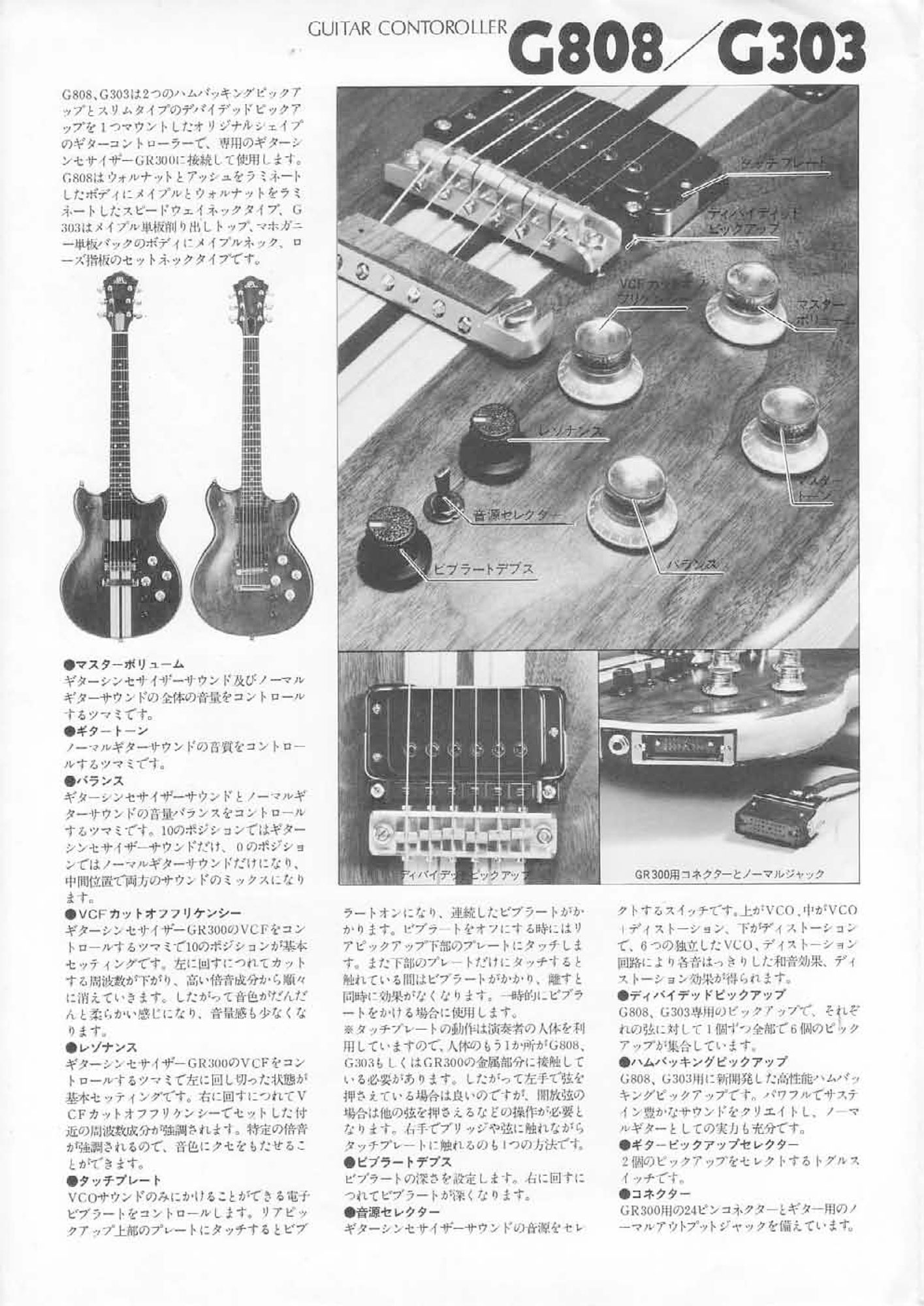
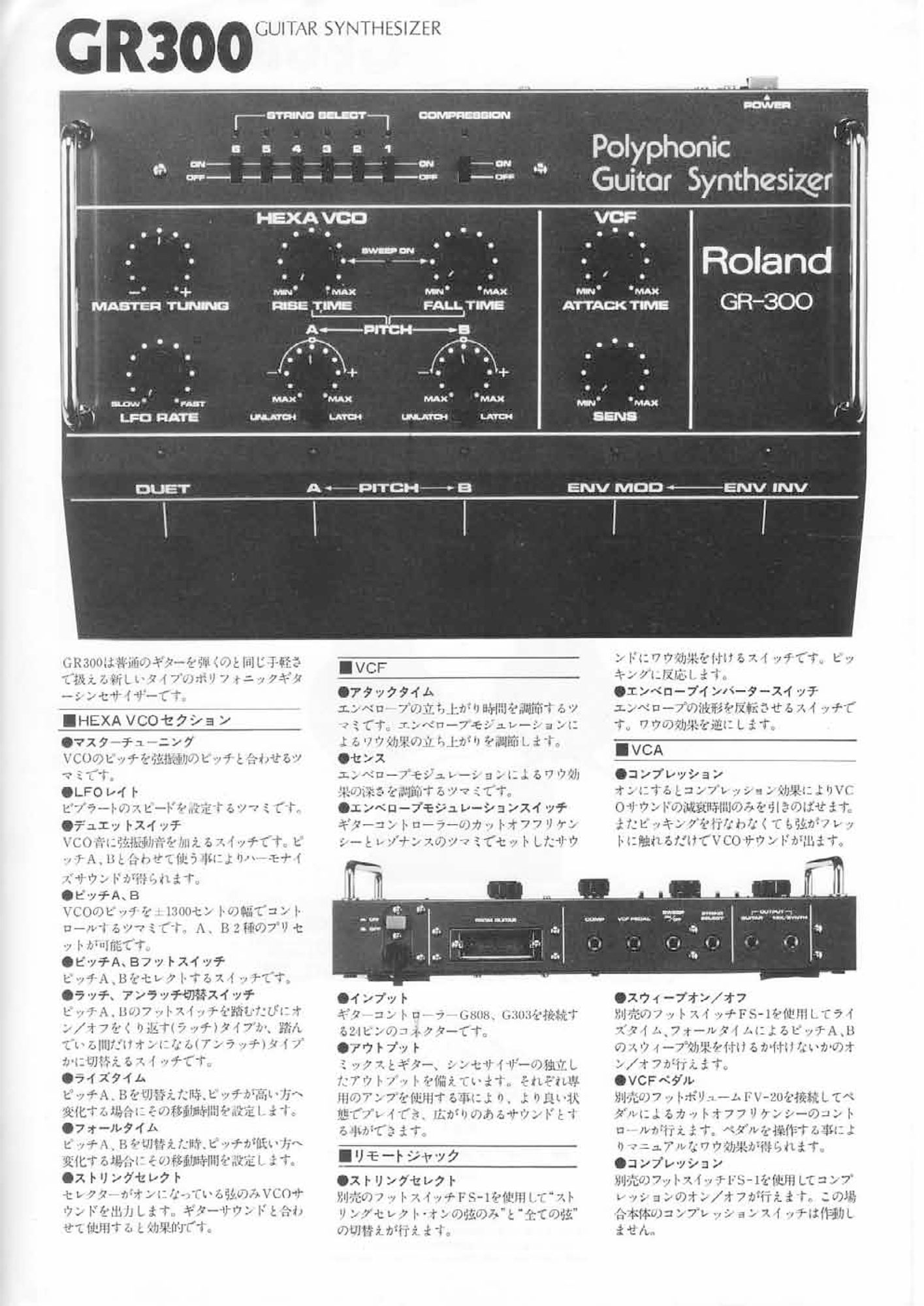
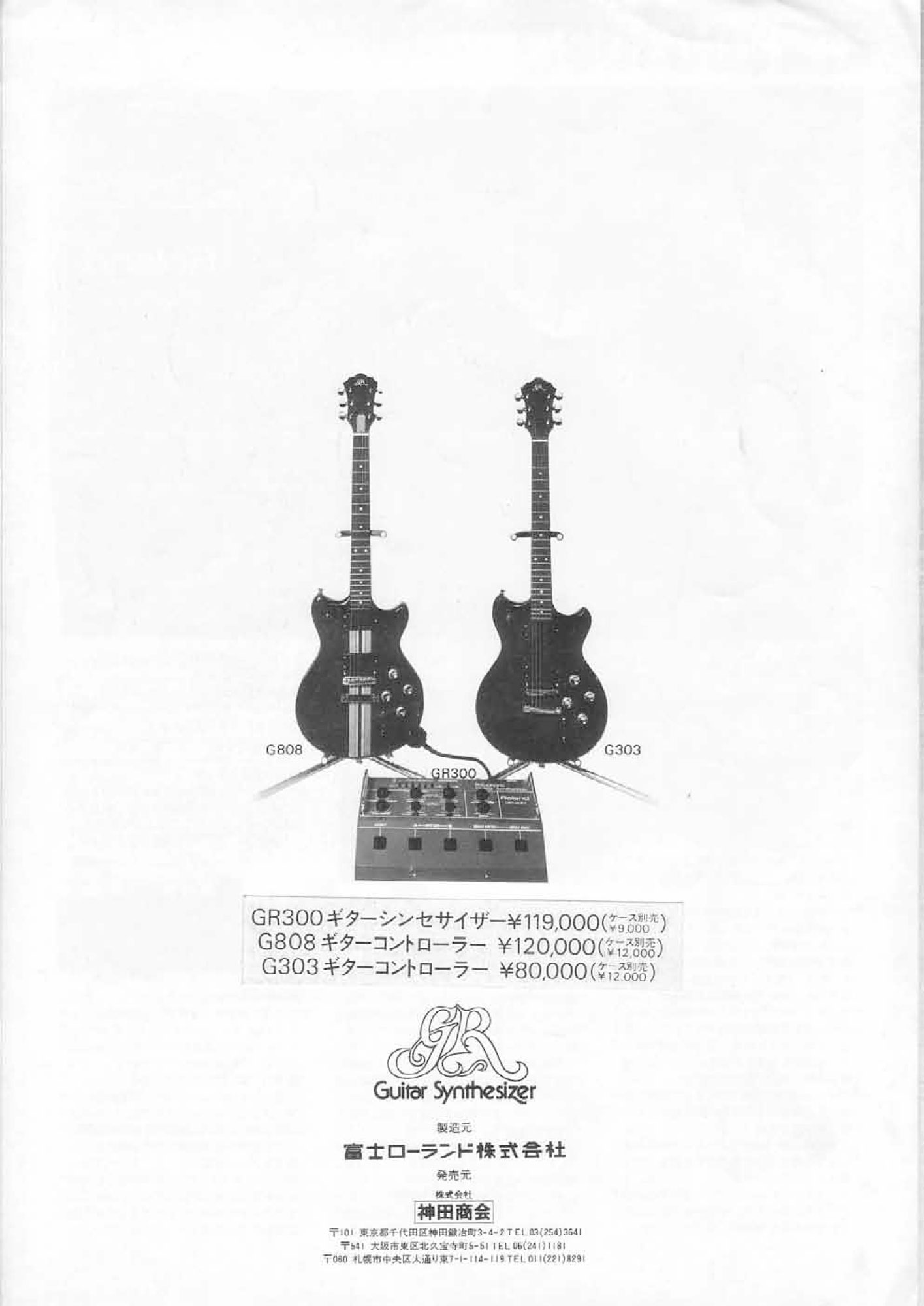
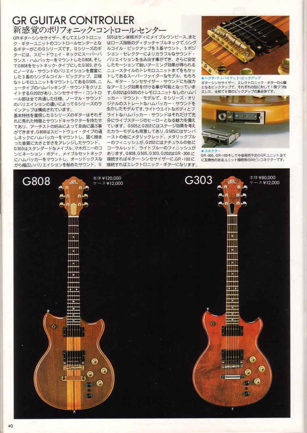
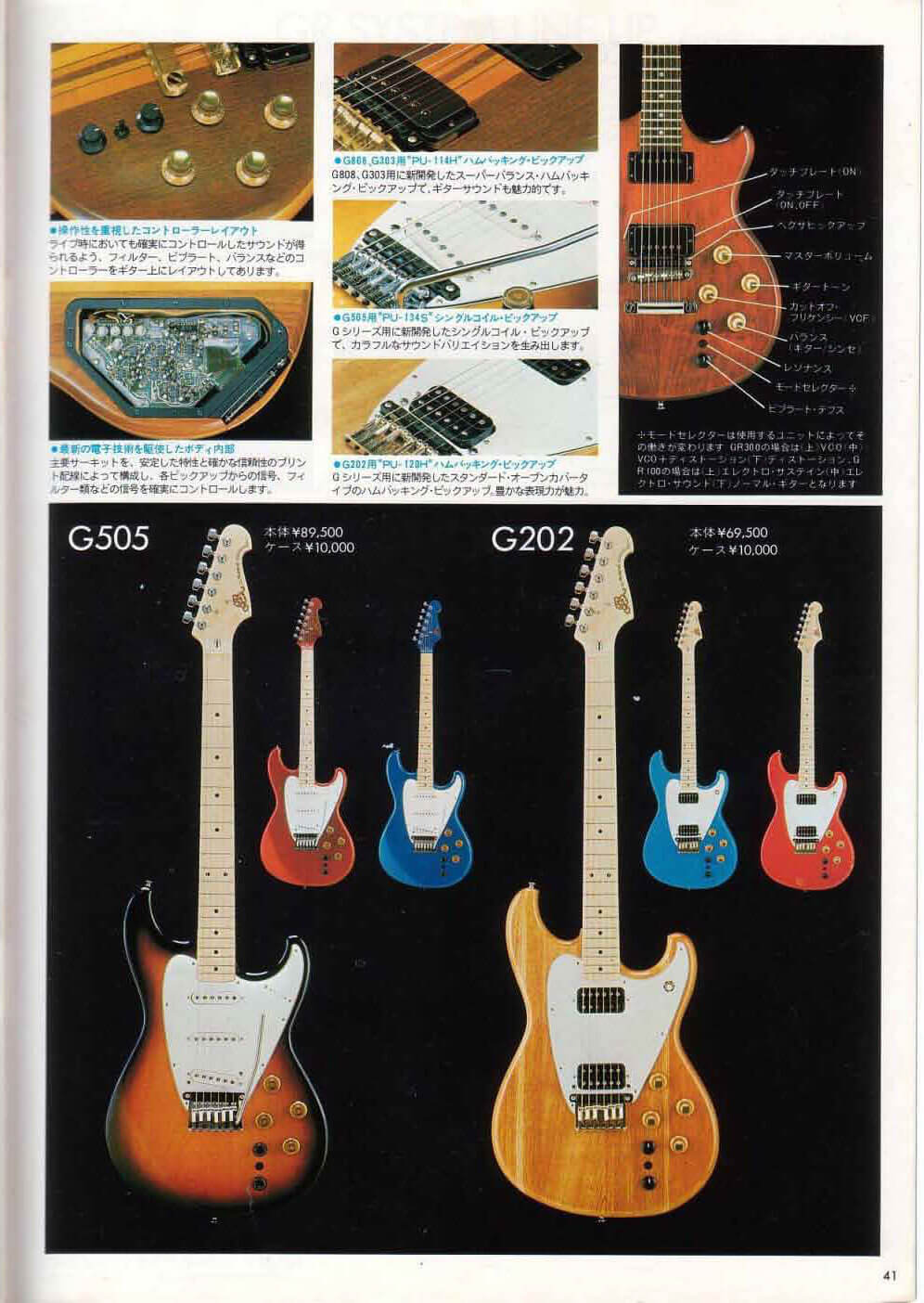
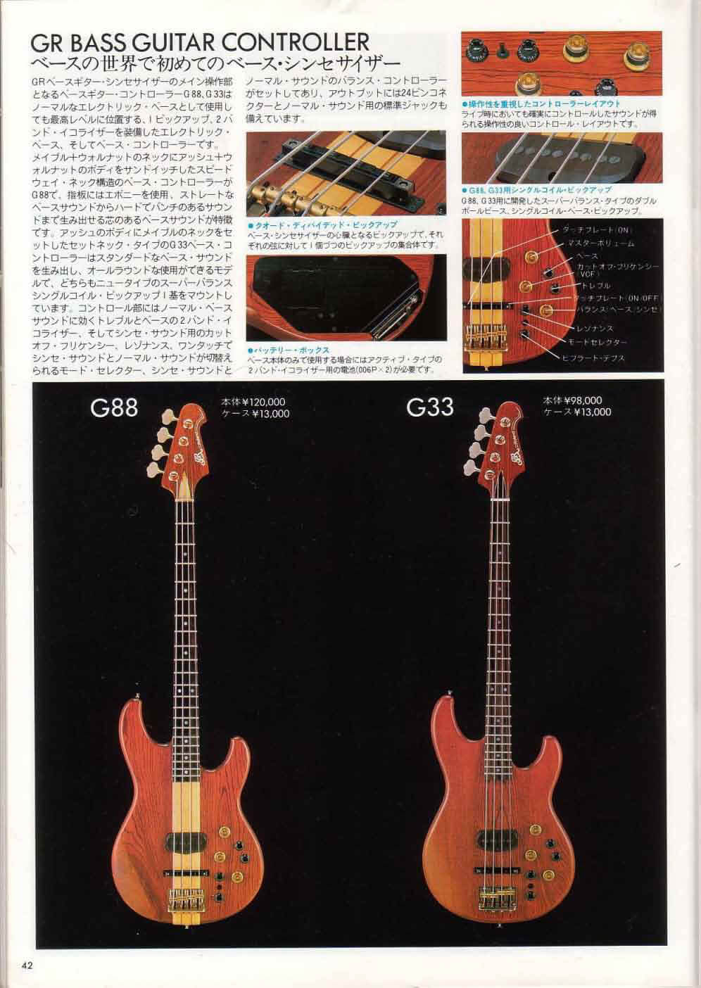
Japanese Brochure:
|
|
|
|
|---|---|---|---|
| Click on any image for larger view. | |||
Japanese Greco 1981 Catalog:
|
|
|
|
|---|---|---|---|
| Click on any image for larger view. | |||
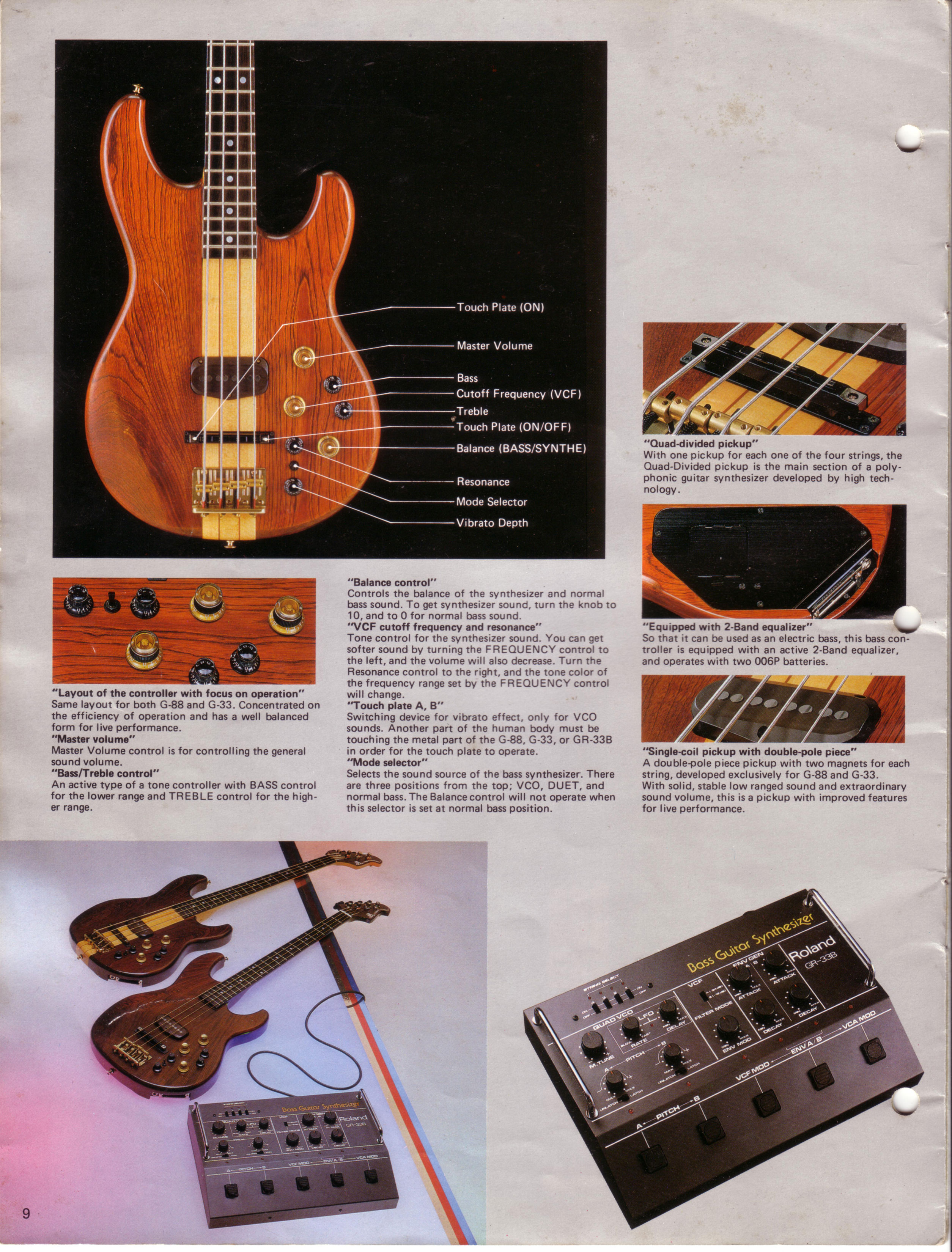
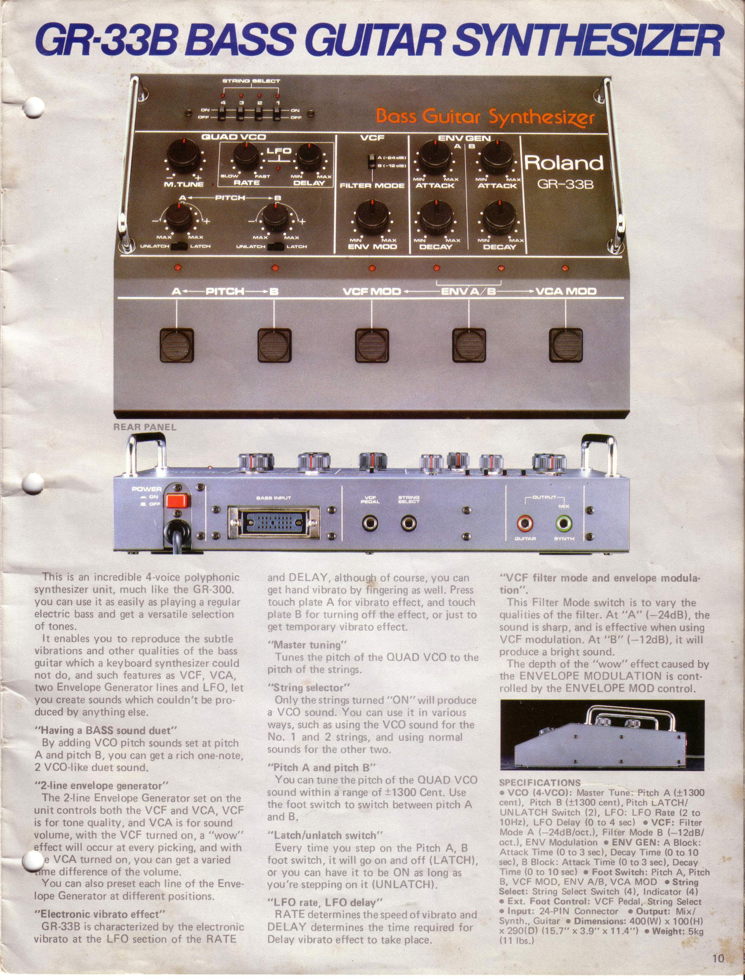
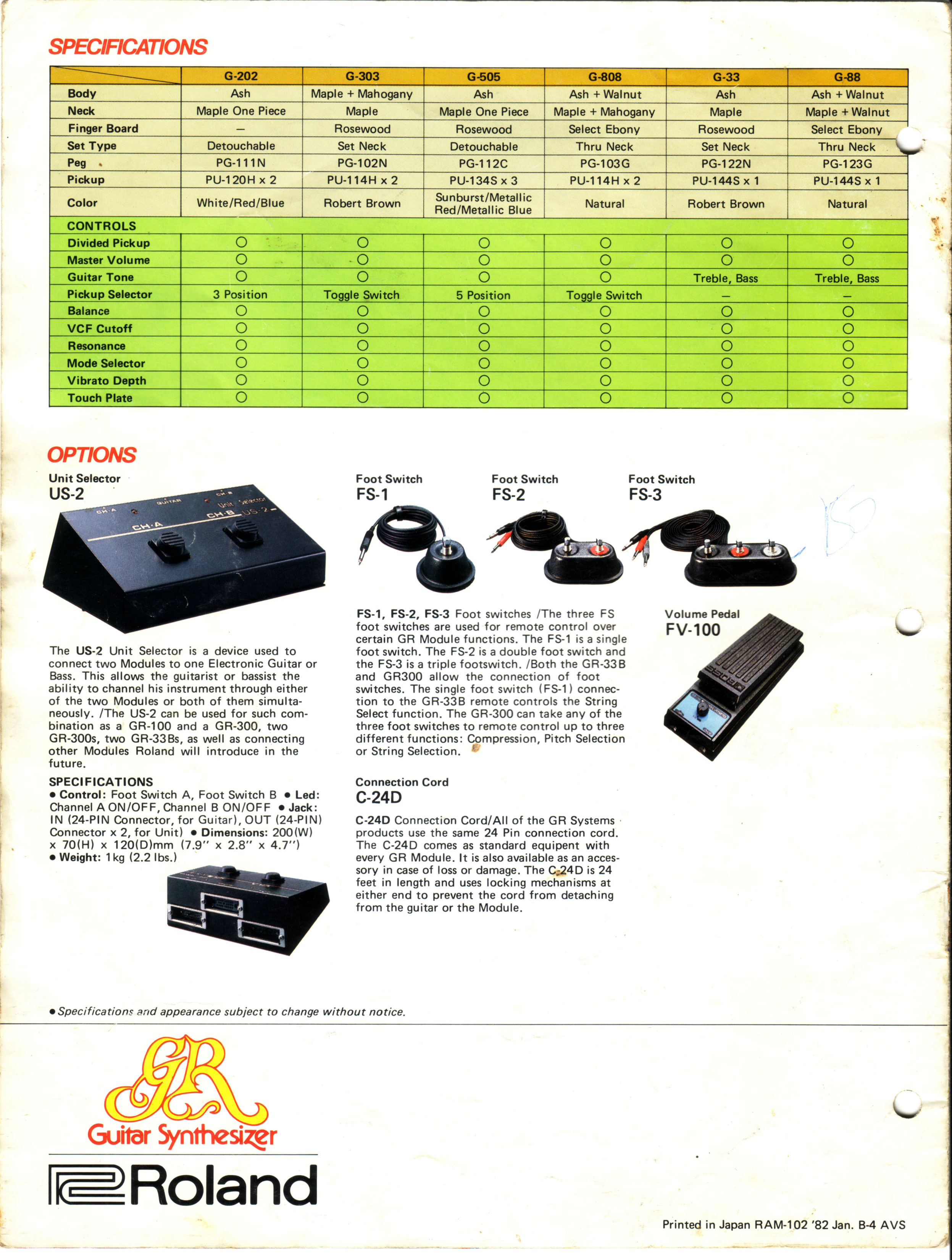
Roland 1982 Guitar Synthesizer Brochure:

|
|
|
|
|---|---|---|---|
|
|
|
|

|
|
|
|
| Click on any image for larger view. | |||
Roland 1984 Guitar Synthesizer Brochure:
|
|
|
|
|---|---|---|---|
|
|

|
|
|

|
|
|
|
|
|
|
| Click on any image for larger view. | |||
Guitar Player 1981 - 1982 Advertising:
|

|
|
|
|---|---|---|---|
| Guitar Player - October 1981 - Click on any image for larger view. | Guitar Player - April 1982 - Click on any image for larger view. | ||
Vintage Roland Gear in UK Magazines:
|
|
|
|---|---|---|
| Click on any image for larger view. | ||
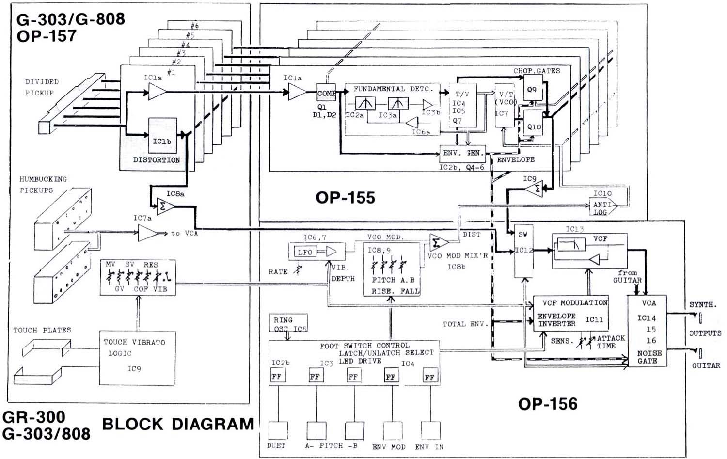
How the GR-300 Works:
Here is a simple explanation of the genius behind the GR-300. I gleaned this information from talking to Mike Bacich, studying the GR-300 service manual, and reading the original GR-300 Patent Application.
1 - Patent Application
|
|
|
2 - The World's Smallest Humbucking Pickup
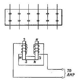
One Roland guitar synthesizer technology innovation is the world’s smallest humbucking pickup. Each element in the Roland guitar synth pickup is actually a tiny humbucking pickup. As you can see, the patent illustration (on the left) depicts a classic humbucking pickup, with dual coils wrapped around opposite magnetic poles. This configuration cancels out noise while amplifying the essential guitar signal. By using tiny humbuckers, Roland was able to apply the incredible amounts of gain needed to take the tiny microvolt output from the pickups to a 25 volt, peak-to-peak signal used to directly drive the Voltage-Controlled Oscillators in the GR-300. Interestingly enough, the earlier GS-500 used what appears to be a collection of six tape machine pickup heads to make the divided pickup. With the G-303/808 Roland introduced the divided hex pickup design still in use today, with minor modifications.
3 - Adaptive Filter
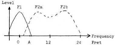
Before the GR-300 can create a synthesizer waveform, the guitar input signal must be filtered to eliminate any overtones and to emphasize the fundamental tone, (or root pitch of the note). After passing through a simple low-pass filter and compression circuit, the guitar input arrives at a two-stage band-pass filter. This adaptive filter changes its frequency response curve depending on what note is played.
When notes are played from the open string to around the sixth fret, the filter takes the shape of "F1", corresponding to the fundamental of the open string. This filter attenuates 1st overtones or harmonics by 24 dB. As higher notes are played on the guitar, the filter response curve shifts to shape "F2a" and "F2b."
4 - Square Wave to Sawtooth Wave to GR-300 Wave
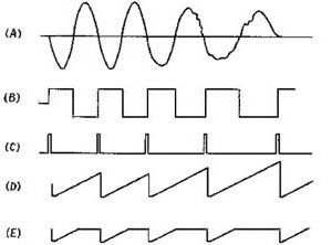
Other guitar synthesizers used different methods to try to detect the peaks of a waveform. The idea is that the time between waveform peaks will determine the pitch of the note played on the guitar. Roland took a different approach, and is probably the only company that tried zero crossing techniques to detect the pitch of a guitar signal. While it is possible to have several zero crossings in the guitar cycle (resulting in octave jumping), the adaptive filter is so efficient that this rarely happens. Here is an explanation of the diagram on the left:
A. Raw input guitar waveform
B. Square wave created by processing the input waveform through filtering and zero crossing circuit.
C. 1 uS pulses created by the leading edge of the square wave
D. Sawtooth waveform created by 1 uS pulses.
E. Distinct GR-300 waveform after "chopper-gate" clips the top of sawtooth waveform.
The raw guitar waveform is filtered and processed through a zero crossing detector to produce a square wave. The edges of the square wave are then used to create 1 microsecond pulses. As a pulse is received by the waveform generating circuit, a steadily rising voltage is generated by a capacitor. When the next pulse is received, the waveform resets to a value of zero, and the cycle starts all over again. Roland calls this a time-to-voltage circuit. Oscillators are tuned by varying the current to the capacitor, which controls the rate the waveform rises. This design leaves one problem: the lower the pitch of the note, the louder the note is. Notice in the example above the widest oscillator pulse (or lowest in pitch) is also the tallest (or loudest). To keep all the GR-300 notes at the same volume, the circuit uses a "chopper-gate" to basically chop off the tops of the sawtooth waveform. The result is the very distinctive GR-300 waveform, unique among analog synthesizers.
4 - Final Signal Processing
The rest of the signal processing in the GR-300 is very much in the classic analog synthesizer design. The sawtooth oscillator outputs feed into a 24 dB per octave voltage controlled low pass filter. At the same time, signals from the hex pickup are used to drive an envelope generator. The output of the envelope generator provides the control signals for the voltage controlled amplifier. The output from the envelope generator can also be used to modulate the voltage controlled filter, (either in regular or in inverted mode). The final bit of genius in the GR-300 is a circuit Mark Smart describes as a "squelcher" circuit. This is a circuit designed to suppress false notes created by second harmonics. It is perhaps too complicated to summarize here, but if you would like to know more about the gory details of how the GR-300 works, there is no better resource than the GR-300 Service Manual, available from Roland. The Service Manual goes into great detail with additional diagrams and notes. My friend Mike Bacich first pointed out to me that the GR-300 technology could easily be expanded to incorporate more features, such as multiple waveform outputs, square wave, triangle, etc. Mark Smart has gone so far as to start to develop an expanded GR-300 that could be used as a controller for a more powerful analog synthesizer. I do not know if Noboru Suenaga, the person credited with inventing the GR-300 is still in the business, but I want to thank him for his invention, and for all the inspiration his guitar synthesizer has given musicians around the world.