- SY-100 Expression Pedal Shoot Out! Comparing the Roland EV-5, Boss EV-30, Moog EP-3 and Mission Engineering SP-1
- SBC-1324 New Videos Posted!
- BX-13 Do-It-Yourself Cooper tracing and silk screen available for download.
- Roland Centerstage - Roland Makes !t Happen! 1984 Winter Namm - First time ever!
- Boss SY-1000 All About Program and Bank Change Commands - Boss SY-1000 Webpage
- Boss SY-1000 All About Program and Bank Change Commands YouTube Video
- Email Blast Archive! 4 Years Plus of Email Blasts Archived.
- Roland BC-13 Full review on YouTube
- NEW Interior Photos - First time ever!
- The Most Requested GR-700 Patch A breakdown of how to recreate the classic Roland GR-700 Factory Patch 3-5, "Lead II" as used by Glen Tipton of Judas Priest, adding a signature sound to the excellent track 'Turbo Lover'.
- High Res PG-200 Manual (NEW) NEW! I tracked down a mint PG-200 Owner's Manual, newly posted.
- Roland GR-500 MINT Stunning Photos As seen on Reverb! A really stunning example of a Mint Roland GR-500/GS-500 combination. Includes the very, very rare GR-500 case, never seen before!
- The Swallow's Dream is a performance piece made only using sounds from the Boss SY-1000 with an Epiphone Dove Pro equipped with the Graphtech GHOST Acoustic Steel String Midi Kit.
- Mastering Resynthesis with the SY-1000 This video shows how to record the master stereo output of the SY-1000 in the USB audio to a stereo track. In this way many tracks of guitar synthesizer can be recorded and layered to create a final composition.
- Epiphone Dove Pro with Graphtech GHOST Midi Kit In this video I share a few insights about a Epiphone Dove Studio Acoustic-Electric Guitar Vintage Burst I purchased with the Fishman Sonitone and Sonicore System and the Graphtech GHOST Acoustic Steel String Midi Kit installed.
- Roland GM-70 MIDI Polyphonic Expressions: Using the vintage Roland GM-70 with the Arturia Pigments Soft Synth with MPE MIDI Polyphonic Expressions
- Roland GM-70 Alternate Tunings and MIDI Continuous Controllers: Using the vintage Roland GM-70 alternative tunings, and assigning MIDI continuous controllers
- Roland Hardware GR-700: Vanguard to Synth Frontiers: Announcing the Roland GR-700! From the Roland Users Group, Volume 2, Number 4
- Boss SY-1000 On The Run Sequence - Step By Step Tutorial - EMS Synthi AKS - Analog Recreation: This is a step-by-step tutorial showing how to recreate the famous 'On The Run' sequence from Pink Floyd's album The Dark Side of the Moon.
- Boss SY-1000 Guitar Synthesizer Sequence Step By Step Dynamic Synth Tutorial: Tutorial on using the Sequencer in the Boss SY-1000.
- Jeff Baxter - How I Became An Electronic Musician: Read this interview with guitarist Jeff Baxter from the first issue of the Roland User's Group Magazine.
- Boss SY-1000: Resynthesis - YouTube Video: Multitrack Guitar Synthesis Recording
- Boss SY-1000 Reaktor 6 - DIY Build Your Own Guitar Synth YouTube Video: Use Reaktor with the Boss SY-1000 to build your own software guitar synthesizer.
- Korg MS-03 Forget MIDI! Forget the Hex Pickup! Direct Guitar to Analog Synthesizer with the mighty Korg MS-03 and the Arp Odyssey and Behringer K-2 (Korg MS-20)
- Korg MS-03 Video - Demo of the RareKorg MS-03 with the (Korg) Arp Odyssey and the Behringer K-2 (MS-20 Clone)
- Roland SPV-355 Guitar to Synthesizer Video - Roland G-303 Direct to the Roland SPV-355
- Behringer K-2 Guitar to Synthesizer Video - The hidden Guitar Synthesizer in the Behinger K2!
- GR-700 Tech Tips from Roland! Originally published in the Roland User Group magazine, Volume 2, Number 4.
- GR-700 Performance Tips! Originally published in the Roland User Group magazine, Volume 3, Number 3.
- Guitar Greats and the GR-700 Originally published in the Roland User Group magazine, Volume 2, Number 3.
- Roland Hardware - GR-700 G-707 Originally published in the Roland User Group magazine, Volume 2, Number 3.
- Synth Ethics Featuring the Roland GR-700 Tips on using the GR-700 from Mark Wood, Guitarist Magazine May 1985
- Three Favorite GR-700 Patches By Steve Carnelli, Guitar PLayer June 1986.
- Roland GR-700 Guitar Synthesizer Product Review By John Themis Guitarist May 1985
- Pat Metheny and Lyle Mays Interview - 1989 Pat and Lyle interviewed during the height of the popularity of the Pat Metheny Group in Music Technology Magazine.
- Pat Metheny Interview - 1985 Vintage interview from the era of 'First Circle', and 'The Falcon And The Snowman' - Guitarist Magazine
- Pat Metheny Interview - 1984 Vintage interview from the Roland Users Group covering Pat's early career as musician and highlighting the Roland GR-300.
- Boss SY-1000 Recreating the Pat Metheny GR-300 Solo Sound YouTube Video detailing tweaks to recreate the dramatic Pat Metheny GR-300 solo sound with the Boss SY-1000.
- Pat Metheny - New England Digital Synclavier Demonstration YouTube Video Old Grey Whistle Test - Roland G-303
- Pat Metheny with NED Synclavier Prototype YouTube Video Early Guitar Synthesizer Controller
- Pat Metheny and the NED Synclavier Read Pat's notes on using guitar synthesizers and the New England Digital Synclavier.
- Van Halen Michael Anthony Roland GR-33B G-33 Bass Guitar Synthesizer Solo YouTube Video From 1982 Largo and 1983 Devore In Concert Live Performance! FILTER SWEEPS!!! DELAYS!!!
- Spicetone 6Appeal Guitar Processor Analog Hexaphonic Distortion Pedal The Spicetone 6Appeal is a modern take on the poly distortion, hexaphonic (hex) fuzz pedal.
- GR-100 GR-300 Power Supply Repair New video on the one GR-100 or GR-300 or GR-33B power supply mod you MUST do!
- Roland GR-D Interior Photos: First time on the web! Interior photos of the Roland GR-D!
- Gibson Les Paul Custom LPK-1 Repair In depth step-by-step repair of the Gibson Les Paul with LPK-1 kit.
- Roland G-303 A Fresh Look! Trevor Harley sent me these photos of his Roland G-303. The guitar was refinished with a flame maple top and back by the Canadian Luthier George Furlanetto. Note that the touch pads have been relocated below the bridge pickup.
- Steinberger Time! Newly posted photos of a White Steinberger GL-4T-GR
- Ultimate 24-Pin Custom Guitar Stunning photos of the most amazing custom built 24-pin guitar ever made! The solar system on the fret board and more!
- More PINK Please! Hamer Phantom A7 Nothing says vintage 80s guitar styles link a solid pin finish! Samuel Cuevas sent me a few photos of this very, very rare pink Hamer Phantom A7 Roland-Ready guitar.
- Boss SY-1000 with Roland G-33 YouTube video with a demonstration of all 200 Bass patches for the SY-1000
- BAK-1 Videos A new video on the BAK-1 Electronics card, plus comparison of the G-88 and G-77 electronics
- BAK-1 Photos Newly posted photos of the BAK-1 Bass Guitar Synthesizer Installation Kit
- Roland G-33 G-88 G-77 BAK-1 Vintage Analog Bass Guitar Controller Assembly - Comparison
- G-77 Fretless First time on the web! New photos from Skylark of his pristine G-77 Fretless bass.
- Clone 24-Pin Cable At long last there is a quality clone of the impossible to find Roland 24-pin cable. This is a quality, made in the U.S.A. cable produced by 'MagicTrashMan' in North Carolina. Check out the description and video on the cables page.
- Roland GR-500 Mods - Part 1 Thanks to the Phantastic Jimi Photon who pointed me to the March April 1981 Polyphony magazine with the first list of Roland GR-500 modifications.
- Boss SY-1000 All Bass Patches! Complete on YouTube (no talking)!
- Read The Full Interview The year was 1983, and the Police were exploding on the charts. The inventive and adventurous Andy Summers was busy rewriting what a rock guitar player could be. The smash hit "Don't Stand So Close To Me" prominently featured the Roland GR-300, played by Andy with the Roland G-808. Volume 2, number 2, of the Roland Users Group magazine featured a great interview with Andy, reproduced for the first time on the web!
- Read The Full Review Roland shifts direction in 1987, releasing the Roland GK-1 and GM-70. This combo said goodbye to Roland guitars and dedicated guitar synthesizers like the GR-300 and G-808 in favor of a system that could be mounted on any guitar, and used to control any MIDI synthesizer. Read Warren Sirota's review of the GK-1, GM-70, and the MKS-50 and MKS-70.
- Roland GR-500 Mods and Tips! Electronic Musician magazine started life as Polyphony magazine, edited by young writer named Craig Anderton. Seemingly produced by on a single typewriter in the early eighties, this Polyphony article features insights and modifications for the Roland GR-500!
- History of the Guitar Synthesizer Travel back in time, before MIDI, before the Roland GR-700, to the early 1980s, when the Roland GR-300 was the pinnacle of guitar synthesizer technology.
- Steve Howe and Steve Hackett Prog Rock Guitar Titans Teamed up for GTR, Chart-Topping Band Centered around the Roland GR-700!
- Steve Howe Roland Profile A detailed profile of Steve Howe, his Roland G-505 and GR-700 from the 1984 Roland Users Group Magazine
- Boss SY-1000 Tutorial Videos New vidoes on setting up Guitar-To-Midi and blending normal guitar sounds with modeled sounds.
- Washburn JB100 Profile A look at the Washburn Roland-Ready JB100. Detailed photos and videos!
- Lyle Mays Remembering Lyle Mays - New YouTube Playlist with Unreleased Tracks from live Radio Broadcast
- Boss SY-1000 Interior Photos and Unboxing Photos
- Parker NiteFly SA with Factory Internal GK-2A Just Added! A profile of a Parker NiteFly SA with factory Roland GK-2A. Demos with Roland GR-100, GR-300 and GR-700.
- Behringer Deep Mind 12 The New Roland GR-700? Vintage Sounds in a Modern Analog Synth
- GR-300 Case Rare spotting of the Original Roland GR-300 Case!
- Roland Ready Les Paul Photos of Bob Welch's Custom Shop Les Paul Paul with Roland electronics.
- Peter Frampton With Roland G-303 Thank you Eric Fisher for finding this rare live video!
- Picture This 30th Anniversary Release - Wayne Scott Jones Album from November 1989.
- Converting the M-16C into an M-64C - Detailed tips on converting the M-16C into a M-64C with four times the memory capacity!
- Roland G-33 Major Update! 18 new photos, PLUS 4 YouTube videos!
- Switch Roland-Ready MIDI Guitar Complete details on the Switch Wild-IV, PLUS all the Switch Guitars!
- Boss GP-10 and Hex Fuzz Details on great hex fuzz sounds from the Boss GP-10
- Steve Hackett - Roland GR-500/GS-500 Performance - Please Don't Touch From the 'Please Don't Touch' tour, November 8, 1978. Great GR-500 showcase!
- Vintage Roland GR-300 Review from Electronics & Music Maker - Nov 1981
- Roland GR-77B for Reaktor - Download a modeled Roland GR-77B for Native Instruments Reaktor 5!
- Roland GR-700 Blue - Remake with 'GR-300' blue finish, new handles, and handsome natural wood end blocks! Thank you Chuck Nin!
- PG-200 - Updated NOS New-Old-Stock photos of the Roland PG-700, programmer for the Roland GR-700. Thank you Eric Rusack!
- G-707 White Ever wonder what a G-707 would look like redone in a brilliant white finish? With Steinberger folding leg rest!
- 3D Printing Vintage Roland Guitar Parts - 24-to-25 pin Plate - Courtesy of Jusin Casey
- David Gilmour - Solo with Roland STK-1 and GR-700!
- Moog Voyager XL (with Casio MG-510 Cameo) Space Music - Melodic Downtempo, Ambient, Ambient& PsyChill Mix.
- Roland GM-70 Guitar-to-MIDI Converter - Review by Paul White, Music Technology Magazine, April 1987
- Theme from M*A*S*H. Arranged using only the ARP Odyssey for all sounds, synths, drums, efx, etc.
- Ibanez IMG2010 - Owned by George Benson. Rare 'Endorsee' finish with Silver hardware.
- Arp Avatar Review by Paddy Kingsland. Vintage review of one of the very first analog guitar synthesizers, the Arp Avatar - Competitor to the Roland GR/GS-500.
- 24-to-25 Pin Mounting Plate. You can download the newly posted '24-25.dxf' CAD file to make your own 24 to 25 pin mouting plate. I used the company Big Blue Saw to make my 24-to-25 plates from aluminum. The price for a single piece can be expensive, but if you order in quatity the price will drop considerably. Plus, they have specials from time to time!
- Roland GR-100 Samples Sounds. The Roland GR-100 Owner's Manual has a list of "Factory Presets", Sample Sounds, at the end of the Owner's Manual. These sample sounds were intending to give some direction on how to use the GR-100, using features such as Filter Modulation, Chorus, and Vibrato, all served up with the classic hex fuzz sound the GR-100 is famous for. Check out this new YouTube video I posted which goes through the Sample Sounds to get a little flavor of what this vintage 'electronic guitar' synth sounded like!
-
SBC-1324 Roland 24 or 13 Pin Input to 13 and 24 Pin Output
Back in 2009 I was approached by a very talented Canadian guitarist who wanted to be able to control both vintage Roland 24 pin GR-series synthesizers and modern Roland 13 pin GK-series synthesizers with one guitar, either a 13 or 24 pin guitar.
The SBC-1324 is the unit I built to meet this need. The unit has both 13 and 24 pin inputs, and a master analog switch to select between the two. There are six amplifiers for each string input, used primarily to boost the 13 pin signals to the 24 pin format, but they can also be used individually to amplify any single string input, whether 13 or 24 pin.
-
Artist Highlight: Neal Schon
Journey guitarist Neal Schon was frequently seen in the early eighties playing a Roland G-505 guitar paired with the GR-300. Schon is not usually thought of as a 'Strat' player, much less a guitar synthesist, but he makes great use of the G-505/GR-300. An outstanding track is the tune 'Valley of the Kings', using the 'Duet' mode of the GR-300.
- Roland SIP-300 Fresh Photos! Super clean photos from an auction by Tone Tweakers.
- Roland GR-300 Emulation with Kontakt 5 or Roland SR-JV80-04 / SRX-04 Ultimate Keys / INTEGRA-7. Download a complete Kontakt 5 patch and trigger a GR-300 with MIDI! Or check out a demo of the Roland GR-300 patch created by the legendary Scott Summers.
- UX-20 - 13-Pin Splitter/Distributor with Buffered Guitar Input Schematic
- Pat Metheny writes about on using the NED Synclavier Digital Guitar Option - First Time Online! From the 1984 NED Owner's Manual.
- Steinberger XL2-GR Guitar Synthesizer Controller - Vintage Roland Ready Bass Guitar Synthesizer Controller
- Pedulla MVP-S Guitar Synthesizer Controller - The phantom Roland Ready Guitar Synth Controller!
- GK QuadBox Schematic Build your own GK QuadBox, 1 input, 4 output 13-pin Guitar Synth Signal Distributor - Combined US-20 and GKP-4 clone!
- RC-1324-VR Roland 13-in to 24-pin Converter Detailed schematic on the acclaimed RC-1324. Control vintage 24-pin Roland guitar synths like the GR-700 and GR-300 with modern 13-pin controllers like the GK-3, GK-2A or the Godin series of guitar controllers
- Modulus Graphite Blackknife Special Guitar Synthesizer Controller
- Roland GR-700 Operating System Upgrade New Sounds! Faster Response!!
- Do-It-Yourself DIY Roland and Ibanez Guitar Synthesizer Control Panel Overlays
- The summer NAMM 1985 show was the year when MIDI became accepted as a standard across the industry, and guitar manufacturers unleased a variety of MIDI guitar products not seen since. From Roland to Steinberger to Ibanez to the ultra rare Octave-Plateau Voyetra MIDI guitar, MIDI was everywhere.
- Detailed information on the vintage IBM-PC music production software from Voyetra. Voyetra is the same company that produced the Kat and Kitten analog synthesiers, the ground-breaking Voyetra Eight polyphonic analog synthesizer, and the ultra rare Octave-Plateau Voyetra MIDI guitar.
- WBRA Public Television Music Video featuring Wayne Joness using Voyetra Sequencer Plus - Live Performance.
- Vintage Interview with Jazz Fusion pioneer John McLaughlin about using the Roland G-303 guitar synth controller and the New England Digital Synclavier with Digital Guitar Option
- Details on the amazing Synclavier II Digital Guitar
- East Side West Side by John McLaughlin From the Album Mahavishnu - Transcribed by Steve Vai.
- Vintage 1980 Full Page Roland G-808 Advertisement featuring Bernie Marsden (Whitesnake) - Who knew? Hard rock icon Bernie Marsden with a Roland G-808!
-
Gibson Custom Shop Les Paul "Studio Custom" Roland Ready Synthesizer Controller Update
More pictures on the Gibson Custom Shop Les Paul Roland Ready Synthesizer Controller page, plus an update on the number of models built. - Musico Resynator | Hexsynator - 1980s Pitch and Envelope Tracking Synthesizer with Roland 24-pin Guitar Synthesizer Input - Detailed photo gallery from November 2017 fundraiser at Sound City Studios in Van Nuys, CA.
-
Gibson Custom Shop Les Paul "Studio Custom" Roland Ready Synthesizer Controller
Beyond the standard Roland offerings in the G-X0X series, there are vintage 24-pin Roland-Ready guitars for just about every niche: the Hard Rock Hamer A7, the traditional player's Zion Strat, or the cutting edge Steinberger GL-2T/GR.
But the classic, eternal, "Cadillac" of the series has got to be the Limited Edition 1985 Gibson Custom Shop Les Paul with the Roland LPK-1 Electronics. Every guitar was the product of Gibson's acclaimed Custom Shop in Kalamazoo, Michigan. Kalamazoo made Gibson Les Pauls have been called the 'Holy Grail' of electric guitars. These vintage guitars combine all the craft and musicality with the feature-rich Roland LPK-1 electronics package, the same electronics found in the G-303 or G-808 guitars. - Jazz and the GR-50! Acclaimed Jazz Guitarist Brad Rabuchin rocks the Roland GR-50 in this track 39 Steps: A Spacewalk. This is Space Station MIR, a collaboration with Flugelhorn Horn genius and composer Michael Wetherwax, with Wayne Joness on keyboards and programming. Watch Now on YouTube.
- BX-13 Micro Schematics Yes! At long last! The final schematic for the BX-13 Micro is available on the website! This design incorporates a VCA (voltage controlled amplifier) with an option to select either guitar or hex fuzz as the guitar signal, plus using controller 2 (resonance) as secondary control source acting as a EV-5 pedal.
- At long last the Vintage Roland Guitar Synthesizer Resource site has a full profile on the Steinberger GL-2T/GR Guitar Synthesizer Controller, with unseen schematics, photos and video, with additional information on the GL-3T/GR and GL-4T/GR.
- Musico Resynator | Hexsynator - 1980s Pitch and Envelope Tracking Synthesizer with Roland 24-pin Guitar Synthesizer Input.
- Korg Z3 Patch Editor Adaption for the Korg Z3 - Thanks to Korg Z3 user David for this free software download.
- GS-500 Video Playlist featuring Terje Rypdal - Luc Bertels hipped me to videos of Terje Rypdal using the Roland GR-500 and GS-500.
- Roland GR-700 and GR-77B AB-700 Case - Image gallery with 12 photos of the rare official Roland factory road case.
- Xotica EA-1 with Roland Ready Guitar Graph Tech Ghost Pickups - Detailed information on this very rare, Rland ready 13-pin Acoustic/Electric Roland guitar synthesizer controller.
- Factory Blue Roland GS-500 - Last year while visiting Japan I stumbled upon a factory BLUE Roland GS-500 in a Tokyo music store! Check out the exclusive photos published for the first time.
- Sounds of the GR-77B! New video posted featuring a layered bass combination of the Roland MKS-70 (same sound engine as the GR-77B) and the GR-77B.
- Pat Metheny Extended Interview - I tracked down the original Guitarist Magazine, May 1985, and have posted the complete interview with Pat Metheny. The previous interview was an abbreviated version.
- GR-300 Synthcheck - A detailed 2000 word review from "The Complete Music Magazine", dated November 1980
- Gibson Explorer - Finally! A home for one of the rarer custom Gibson vintage Roland guitar synth controllers
- Jimmy Page - Vintage 1985 magazine ad featuring the guitar legend and his G-707/GR-700 rig!
- LPK-1 Installation Diagram thanks to John Doucette for emailing the scans.
- GK-20 Schematic - 13-pin Guitar Switcher, Schematic ready for download
- Filter/Buffer Schematic - Schematic ready for download.
- Roland GR-700 and GR-77B Updates: From the Roland User Group Archives, a complete MIDI guitar and MIDI bass system profile!
- Roland GR-77B Updates: Finally! The Roland GR-77B and G-77 pages have been updated. Be sure to check out the G-77 page as well.
- Vintage Roland G-505 and GR-300 combination magazine advertisement.
- GR-700 One Step Beyond!: From the 1985 Roland User Group Magazine
- GR-700 4x Memory Expansion!: Easy to do, super DIY Memory Expansion!
- Ibanez IMG2010 and MC1: Updated! High-Res Brochure from 1985
- G-707 Steve Hunter: Vintage Product Review from 1985, Part 2!
- G-707 Steve Hunter: Vintage Product Review from 1985, Part 1
- GR-500 Steve Hackett: Vintage Product Review from 1978!
- GR-500 Patch Sheet: Original Blank Patch Sheet
- GR-500 - Solo Voice Tuning : Adendum on Tuning the Solo Section
- GR-300 Filter Mod: LFO to Filter Modification
- GR-300 Output Mod: Increase the output of your GR-300!
- GR-55 Schematics, Service Notes: Full factory service notes for the Roland GR-55
- Ibanez MIU8: Specs, photos, details on the rarest of rare!
- MIU8 Schematics: Schematics and Service Manual (pdf)!
- Korg Z3 Product Page: From early Product catalog!
- Hamer A7 Guitar: Added to the guitar pages, a tribute to the Hamer Phantom A7! Tubo Lover rocks!
- GR-500 24-pin Connector Change: Documentation of the change from the original, pin-type C24 connector to the much more common C24 positive (locking frame) connector.
Features and Specifications
Introduction
Links
3D Printer 24-to-25 Plate
Photos - Version 1
Photos - Version 2 - Active Electronics
Videos
DIY Roland 24-pin to DB25-pin Conversion
Features and Specifications:
- Use modern, readily available, high quality DB 25 pin cables in place of 25 - 35 year old hard-to-find vintage 24-pin cables
- Works with all vintage Roland Guitar and Basses (G-202, G-303, G-505, G-707, G-808, G-33, G-77, G-88).
- Works with Roland Guitar Synthesizers: GR-300, GR-33B, GR-700, GR-77B and GM-70.
- Download wiring diagram for guitar and synthesizer 24-to-25 pin conversion.
- Basic soldering skills required.
- SOLD OUT!
 |
|
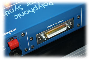
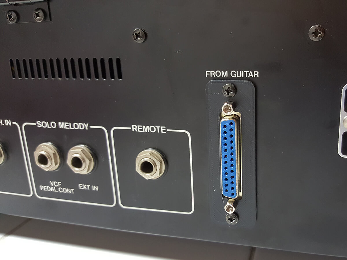
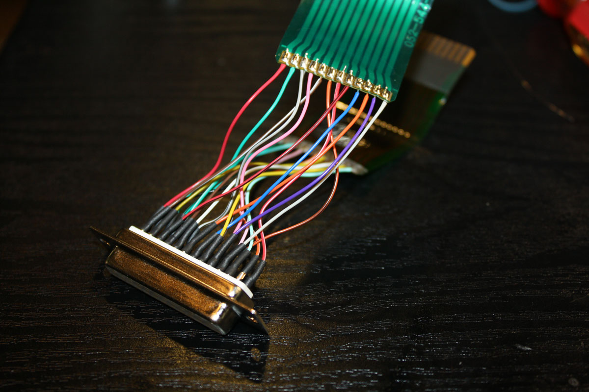
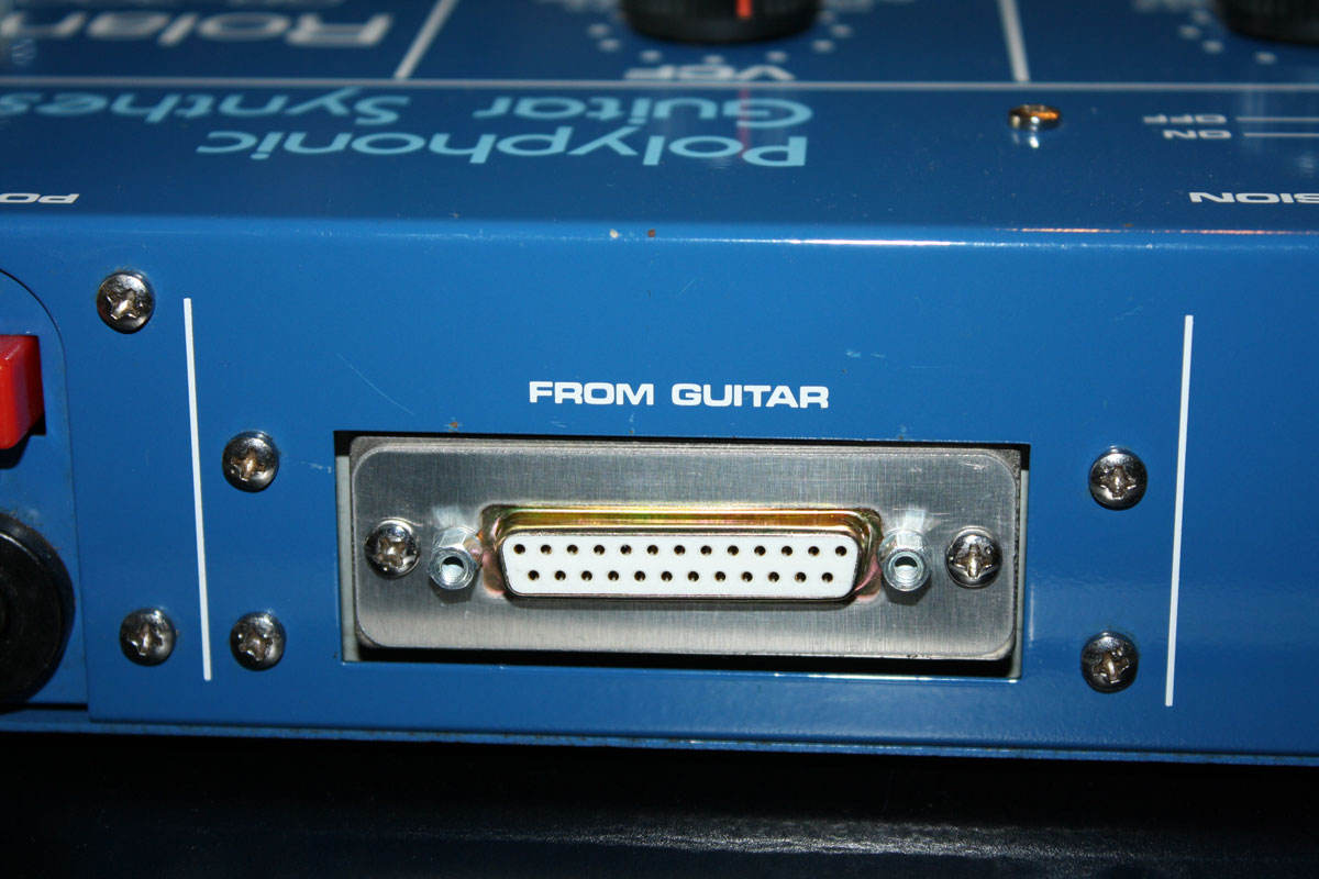
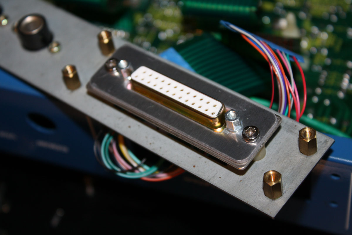
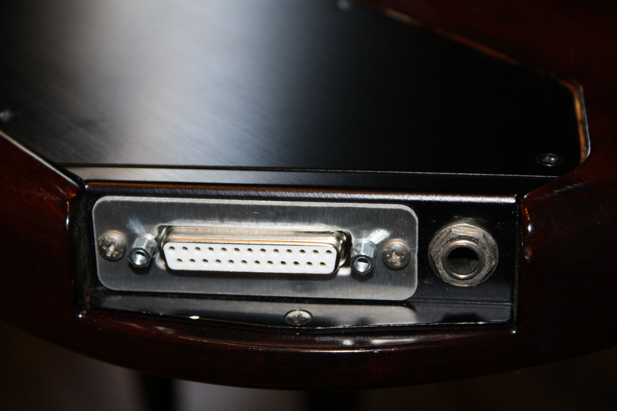
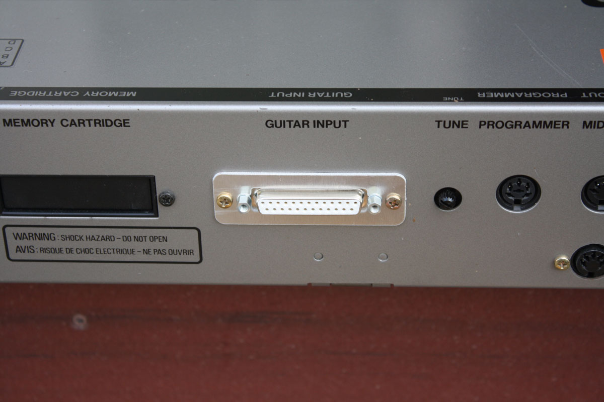
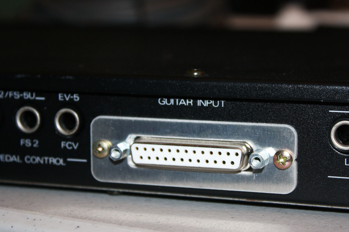
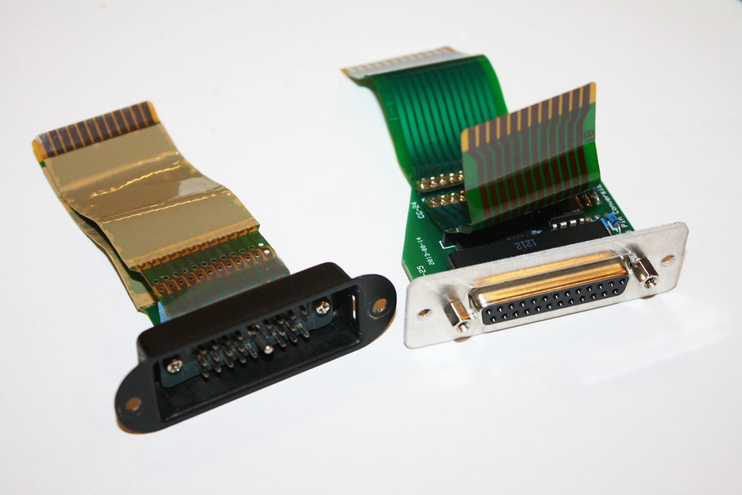
GR-300 with DB25 Connector in place of original
proprietary 24-pin connector. |
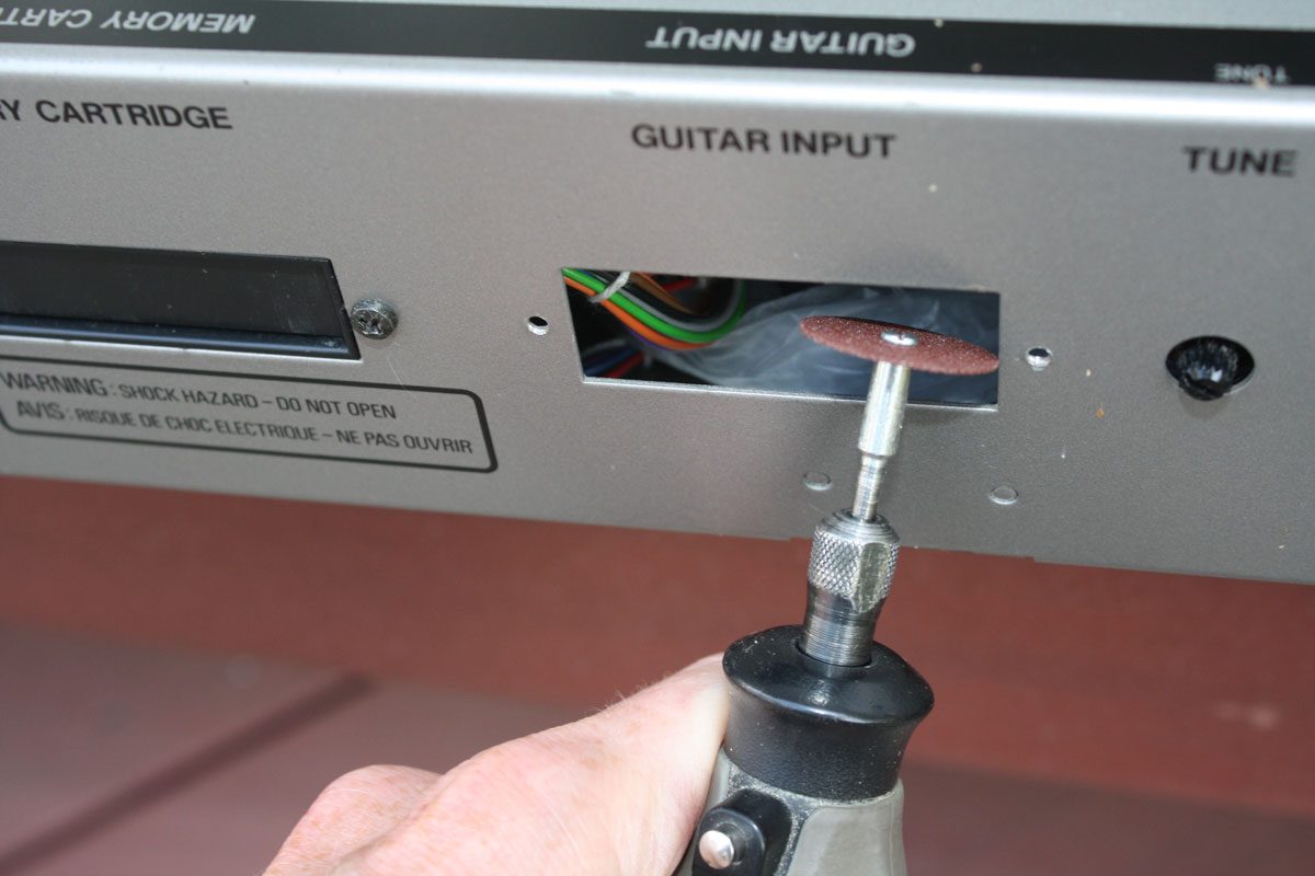
Introduction to the "Do It Yourself" Roland 24-pin to DB25-pin Conversion:
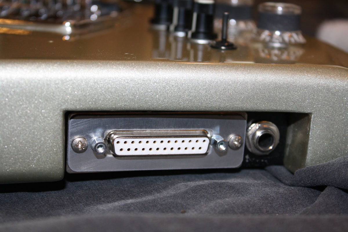
Download 24-to-25 stl (3d Printing)Vintage Roland guitar synth players have been replacing the proprietary 24-pin connectors with the more common DB25 hardware for about as long as Roland has been making guitar synthesizers.
For some folks, it did not make sense to keep paying top dollar for the Roland cables, when there is a high-quality, low cost alternative. Now, with the increasing scarcity of the original Roland cables, and the escalating price, it makes more sense than ever to consider moving away from the original Roland hardware.
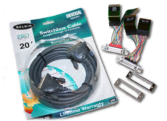
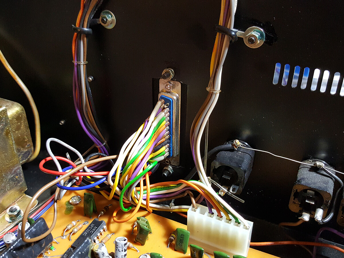
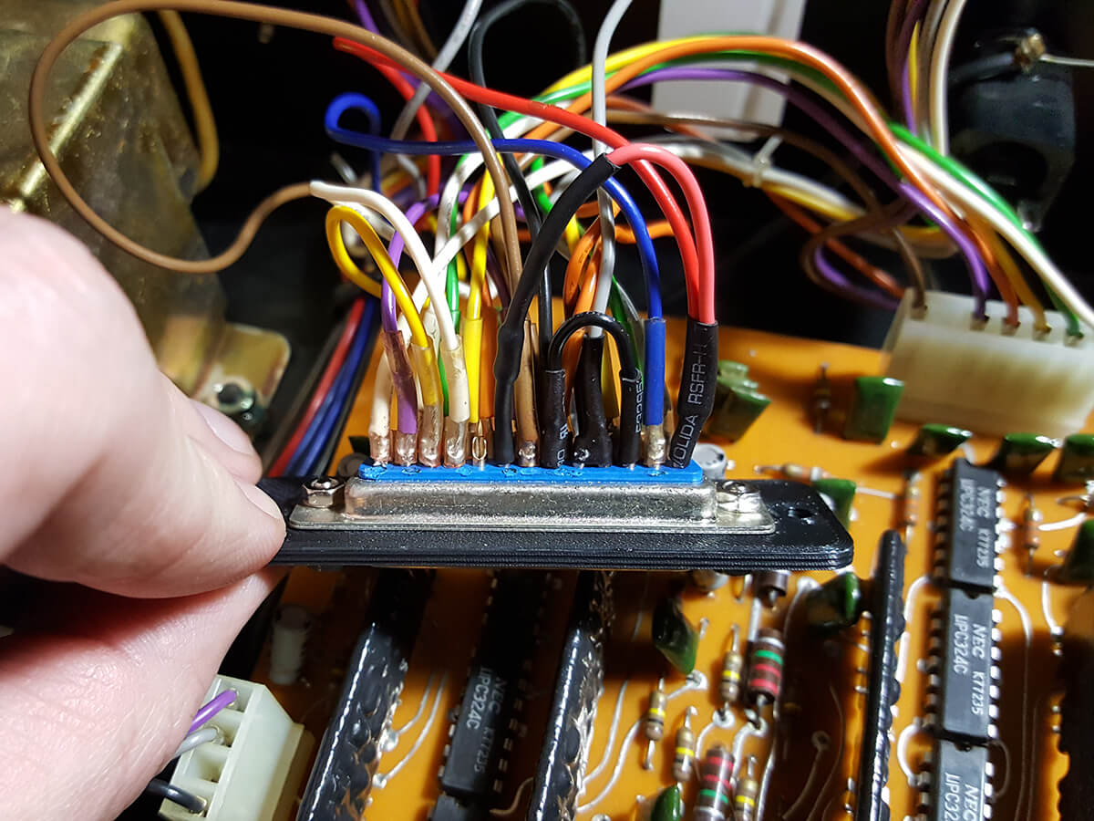
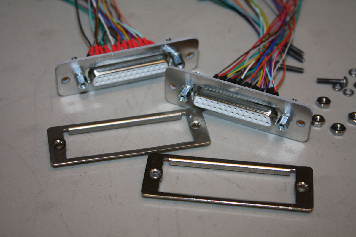
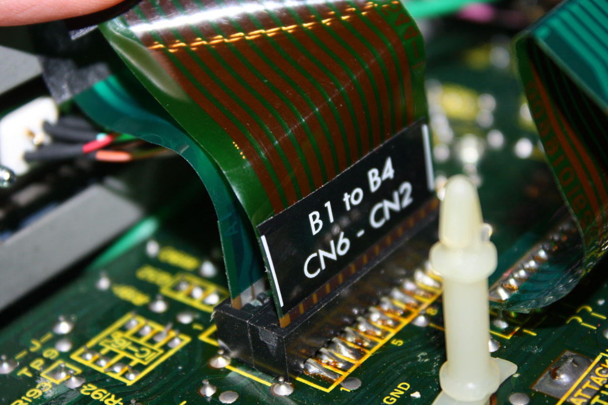
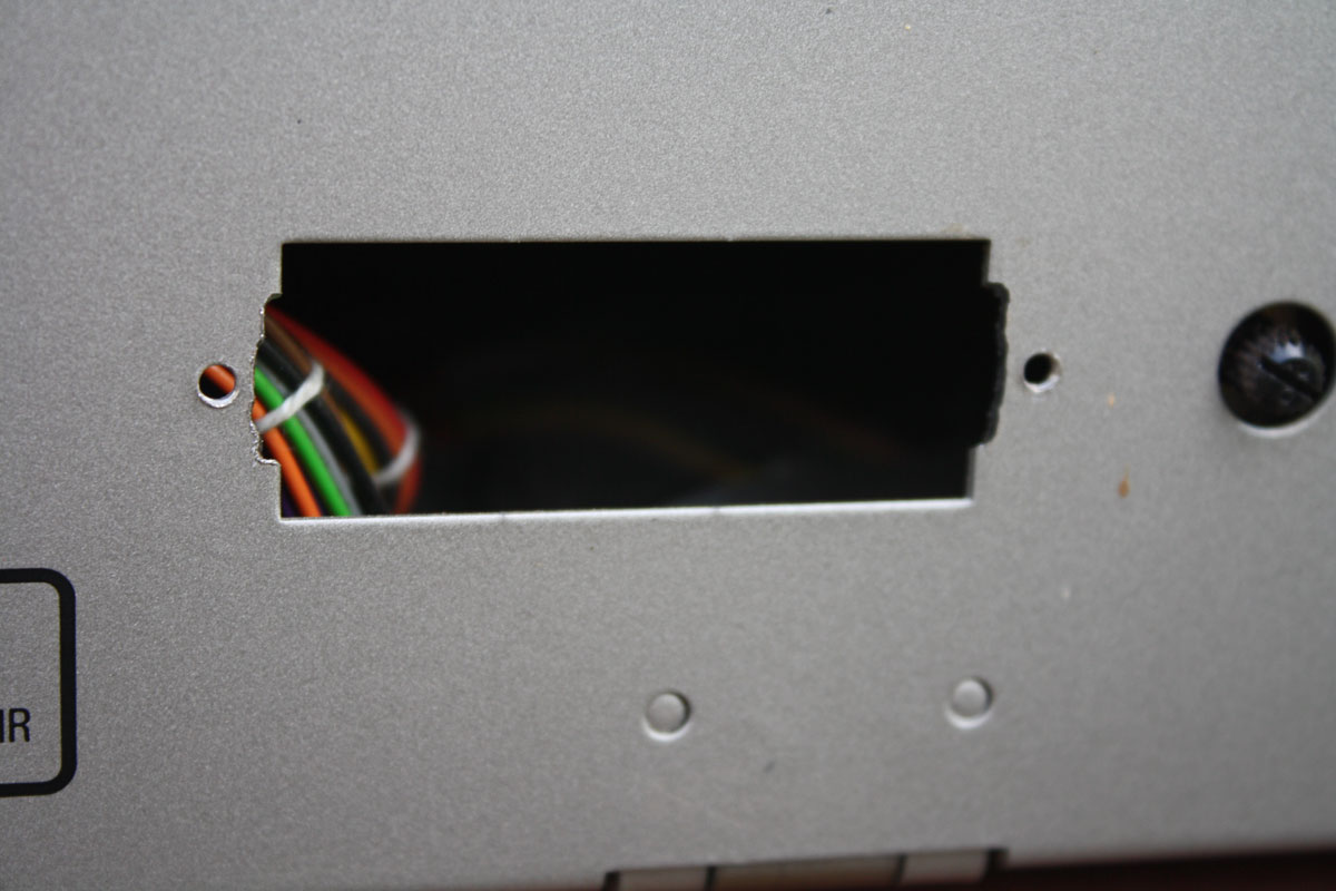
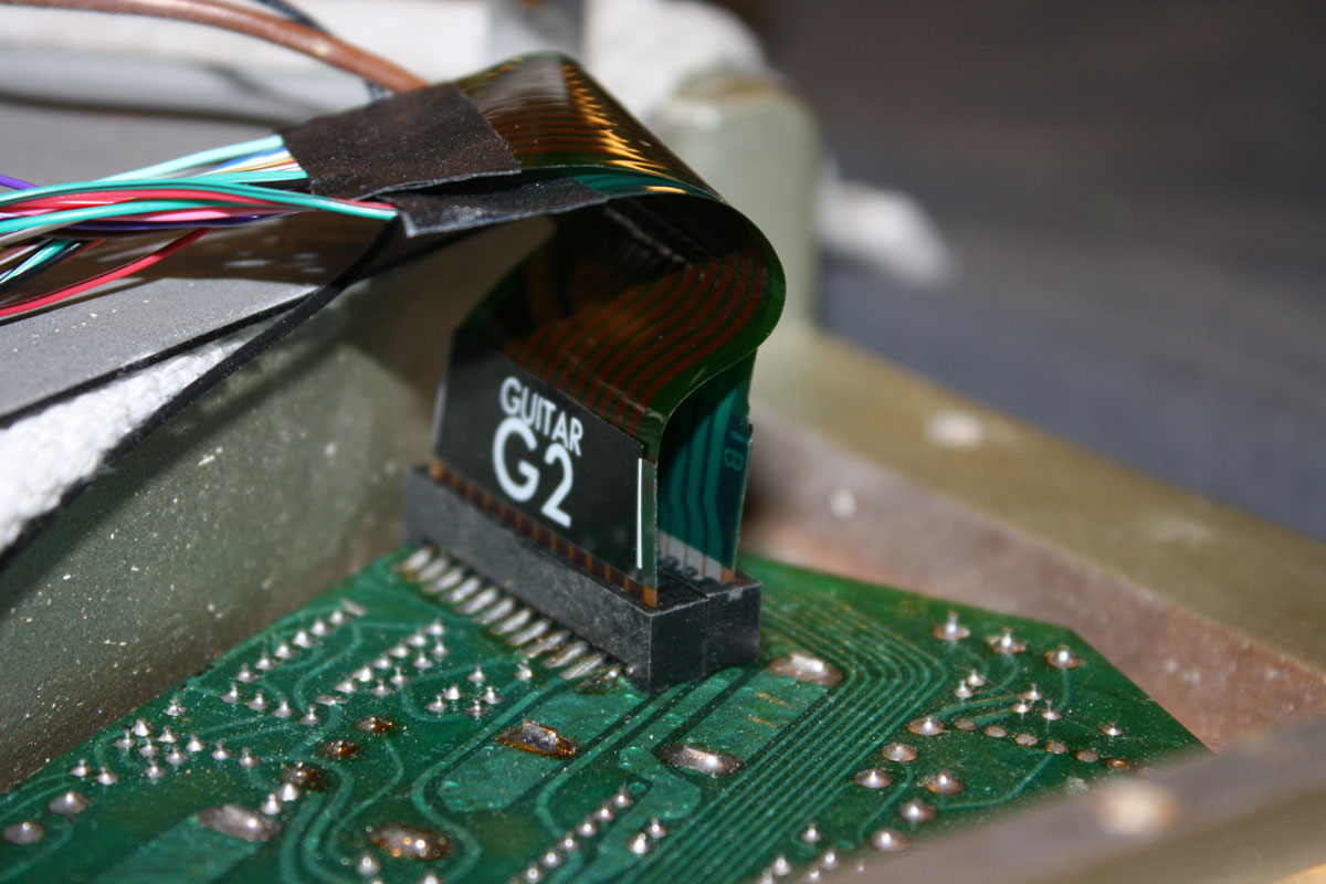
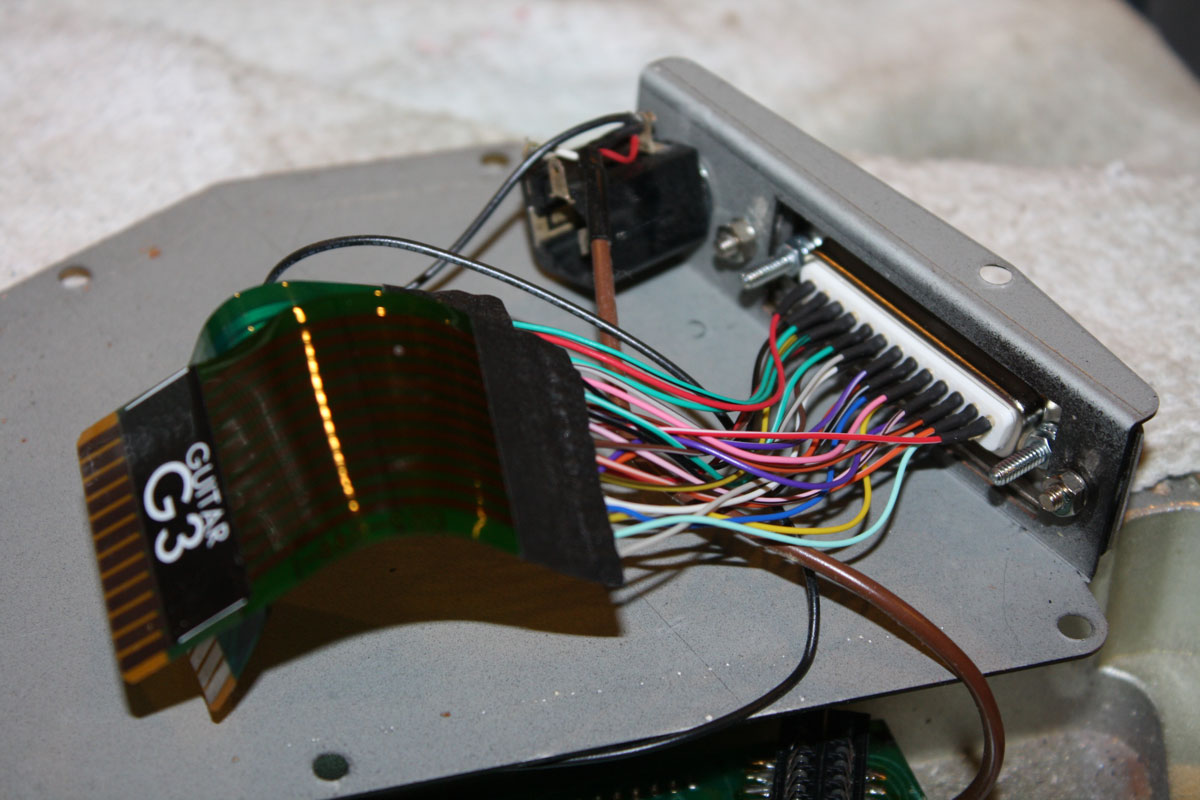
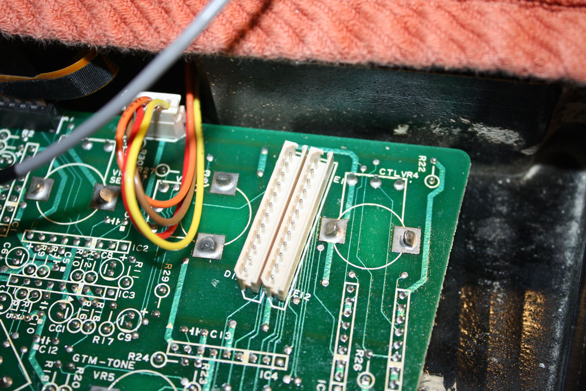
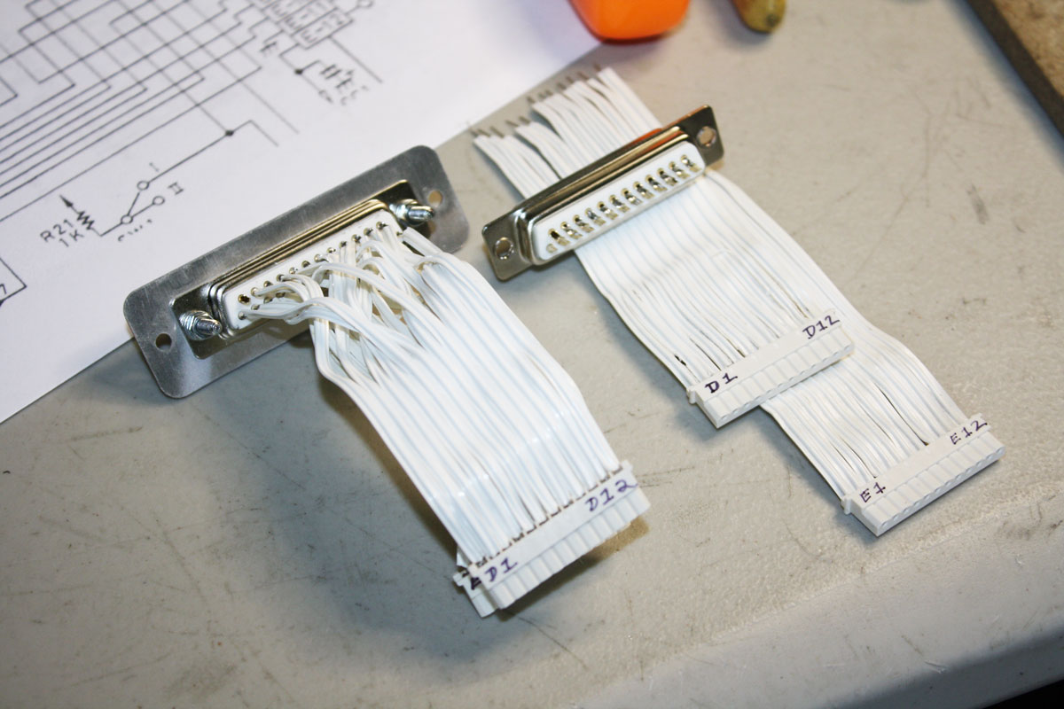
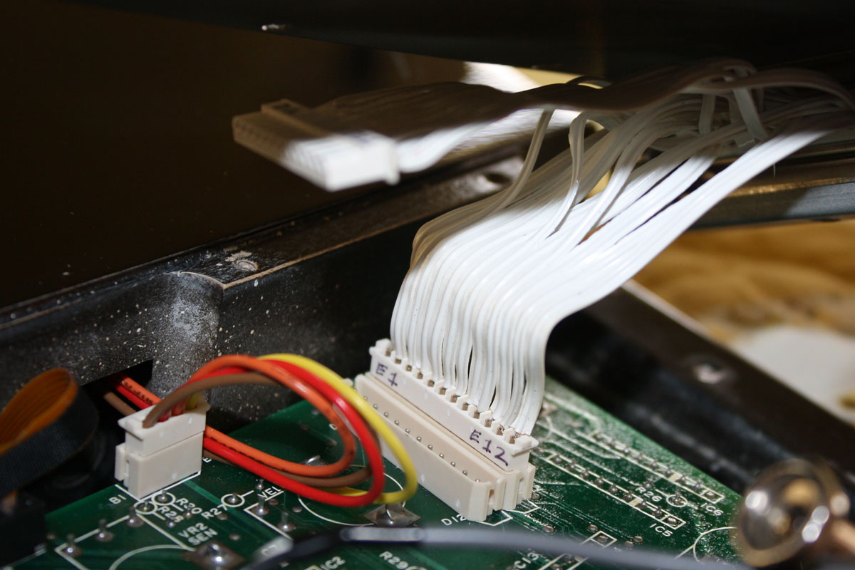
This page outlines a Roland 24-pin to DB25-pin procedure I developed. I started with a surplus of Roland 24-pin ribbon connectors and locking rings. Basically, I connected 24 wires to the DB25 pin connector, then attached those 24 wires to the Roland ribbons removed from the original 24-pin connectors. By using the Roland ribbons, I did not have to make any permanent changes to either my guitars or synthesizers. To keep wiring organized, I followed the Roland pin-outs, so pin one on my DB25 connector is +15 volts, pin two is -15 volts, etc. the same as on the original Roland 24 pin connector. This also maintained compatibility with the Roland US-2 Turbo and the RC-1324-VR.
How to read the 24-to-25 pin diagram:
Switching over to DB25 hardware is not too difficult, though it is important to keep in mind when wiring the connectors the asymmetric nature of the original Roland hardware. The Roland 24-pin connectors had nine pins on either side, plus six pins in the middle, for a total of 24-pins. The six pins in the middle were not symmetrically distributed, so wiring both sides identically will result in incorrect wiring.
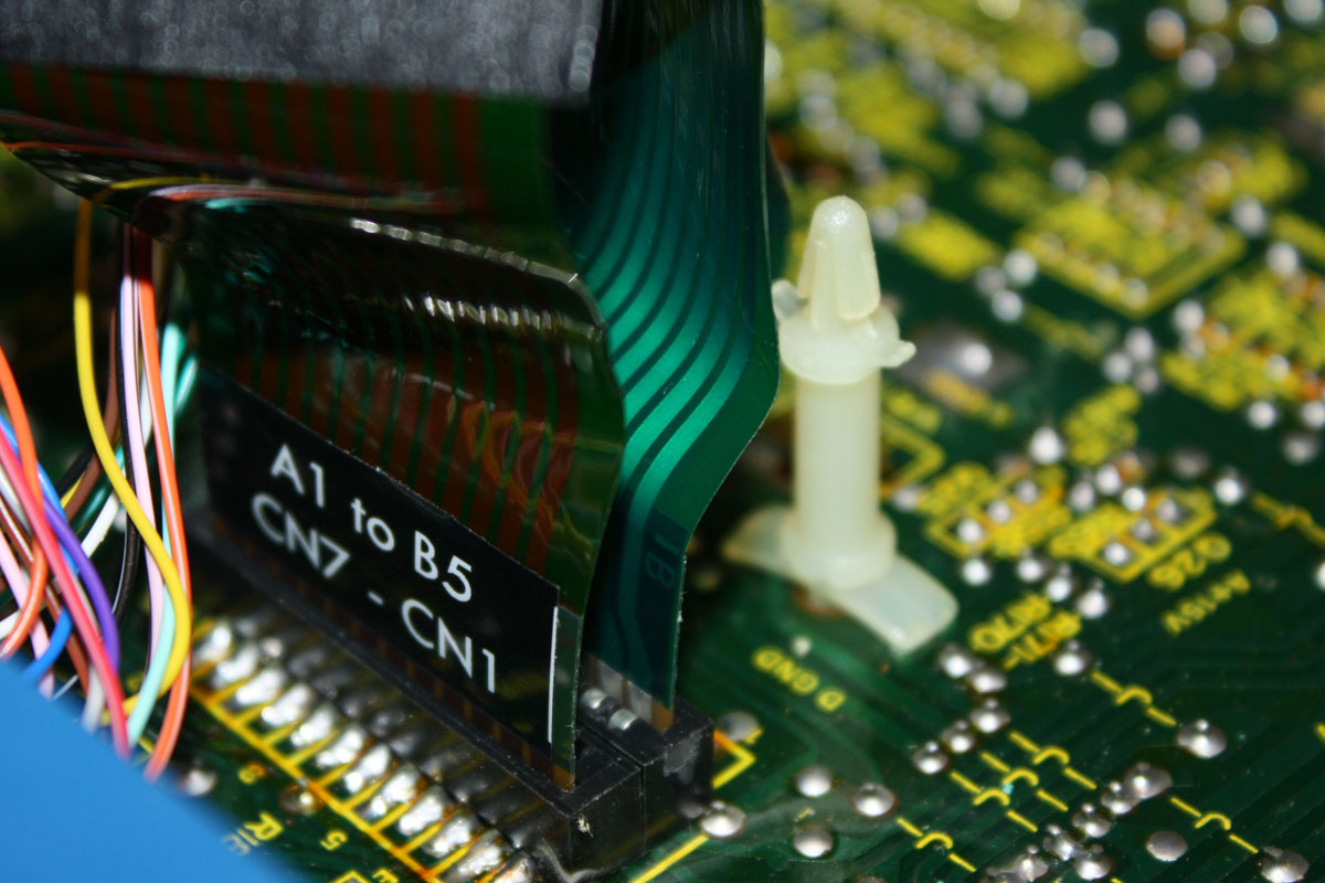
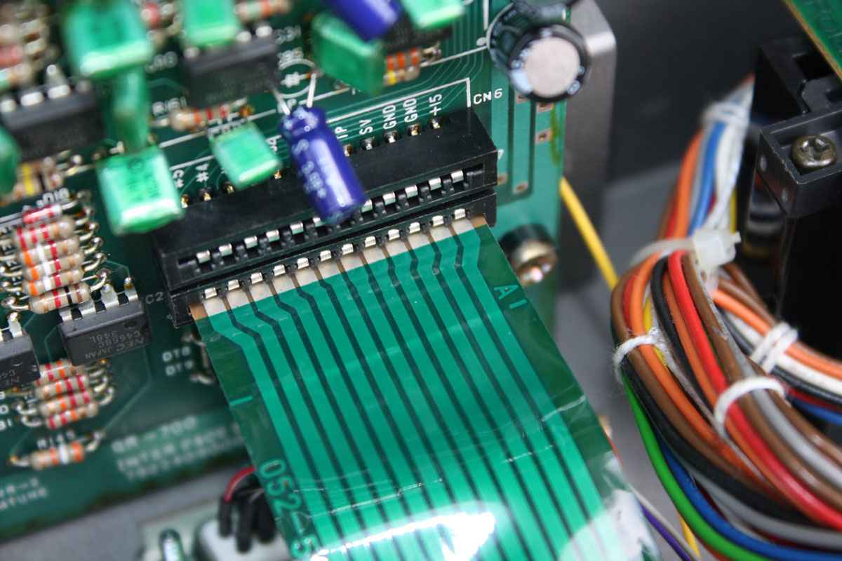
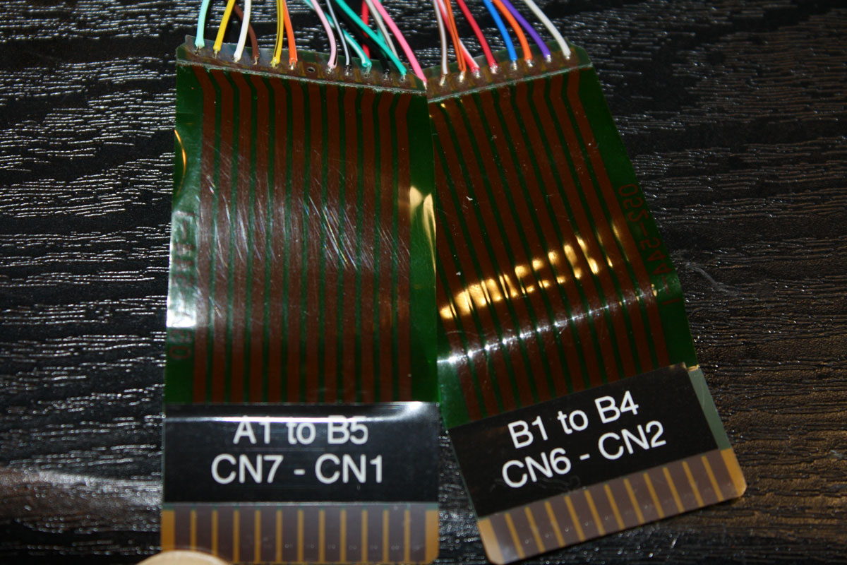
The first page of the diagram outlines creating the connector for the guitar. You will notice the top ribbon, "A1" has twelve solder pads for connecting wires. These are labeled indicating function, original Roland pin assignment, and a color code. For example, the top most pad is labeled as "GND", "Green/Black" and "4". On the original Roland 24-pin connector, pin "4" is one of many pins used for ground. I used a green wire with a black stripe for this connection.
Why does pin "4" come first? If you look at the original 24-pin connector, you will notice that pin "4" is one of the asymmetrically distributed center pins.
The next connection down is labeled as "+15V," "Red" and "1". Pin "1" on the Roland connector is the positive 15 volt power supply. So, on the "guitar" connector, pin "2" on the "A1" ribbon carries the +15 volt supply. If you look at the second page, outlining the connections to the synth, you will notice that the +15 volt supply is now the last connection on the ribbon labeled as "B1."
Follow the pdf diagram, and you will not have any problems. Also, check out the YouTube clip below that I made for a retrofit kit to get an overview of how things were assembled.
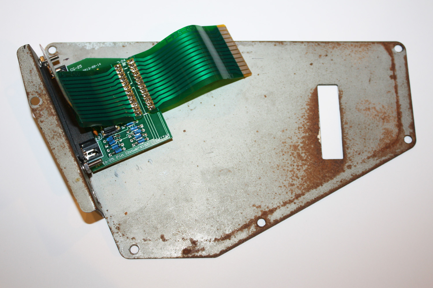
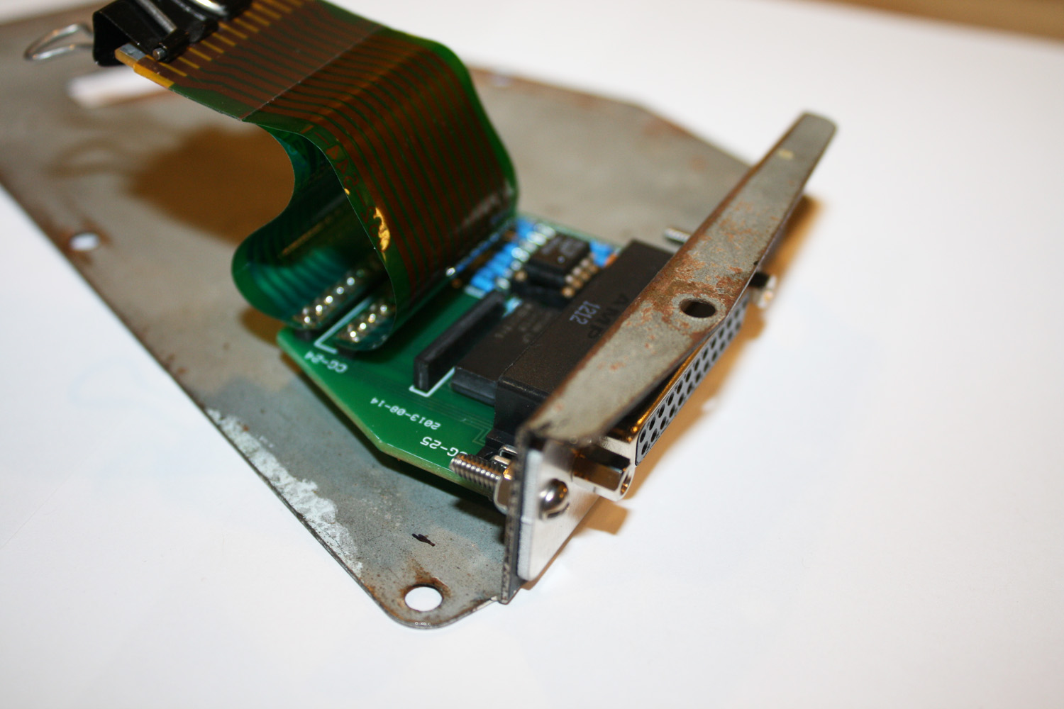
3D Printing Vintage Roland Guitar Parts
What To Do With A STL File? 3D Printing
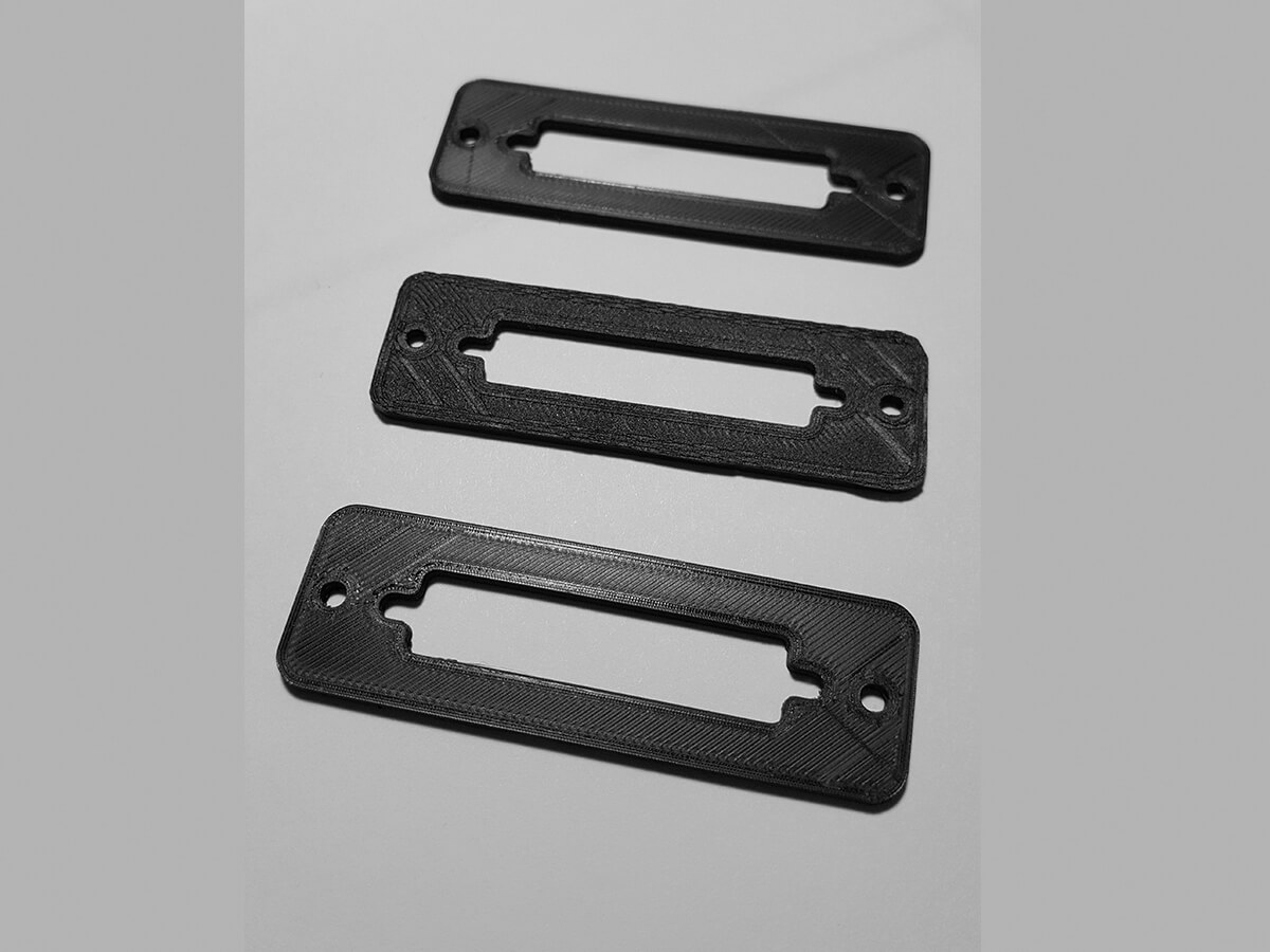
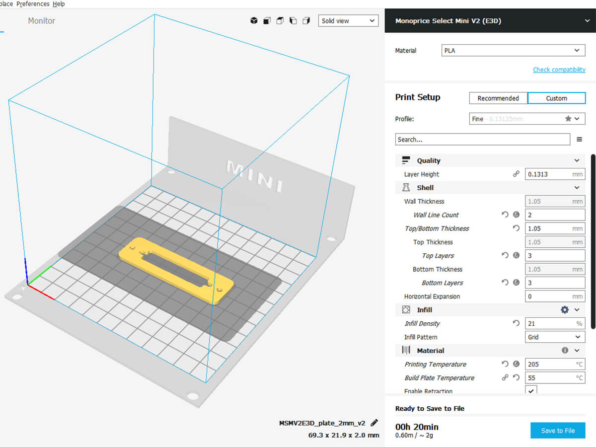
You can use the 'plate_2mm_v2.stl' to make your own 24 to 25 pin mouting plate using a 3d printer. Justin Casey was kind enough to share this file and these photos when doing a 24 to 25 pin conversion for his GR-500.
Justin wrote: "I've attached the standard STL file with a plate at 2mm thick. I've also attached an image of the front and back of the plates, as well as a screenshot of the basic settings I used in the slicer software for my 3D printer. I did these on a Monoprice MP Select Mini V2 with PLA as the material. As an STL is a universal filetype, people can use the file themselves if they have a printer or send it off to a shop to have someone else print it for them. Let me know if you have any questions and I'll try to answer them as well as I can, but I will admit I'm still a relative novice to the world of 3D printing."
Download 24-to-25 stl (3d Printing)24 to 25 Pin Conversion - 3D Printer:
|
|
|
|
|
|
|
||||
What To Do With A DXF File?
You can use the '24-25.dxf' to make your own 24 to 25 pin mouting plate. I used the company Big Blue Saw to make my 24-to-25 plates from aluminum. The price for a single piece can be expensive, but if you order in quatity the price will drop considerably. Plus, they have specials from time to time.
Download 24-to-25 dxf DiagramLinks to more information:
- Download wiring diagram for guitar and synthesizer 24-to-25 pin conversion (pdf).
- Pin-outs for the original Roland 24-pin connectors.
- DB25 pin connector at Mouser.com.
- DB25 pin hardware posts at Mouser.com.
- Amazon - BelkinF3D111-10 Conductor Switchbox Cable (10 Feet); DB25M/M
- Amazon - BelkinF3D111-15 Conductor Switchbox Cable (15 Feet); DB25M/M
- Amazon - BelkinF3D111-20 Conductor Switchbox Cable (20 Feet); DB25M/M
- Downes Guitars webpage on converting a G-505 from 24 to 25 pin configuration.


